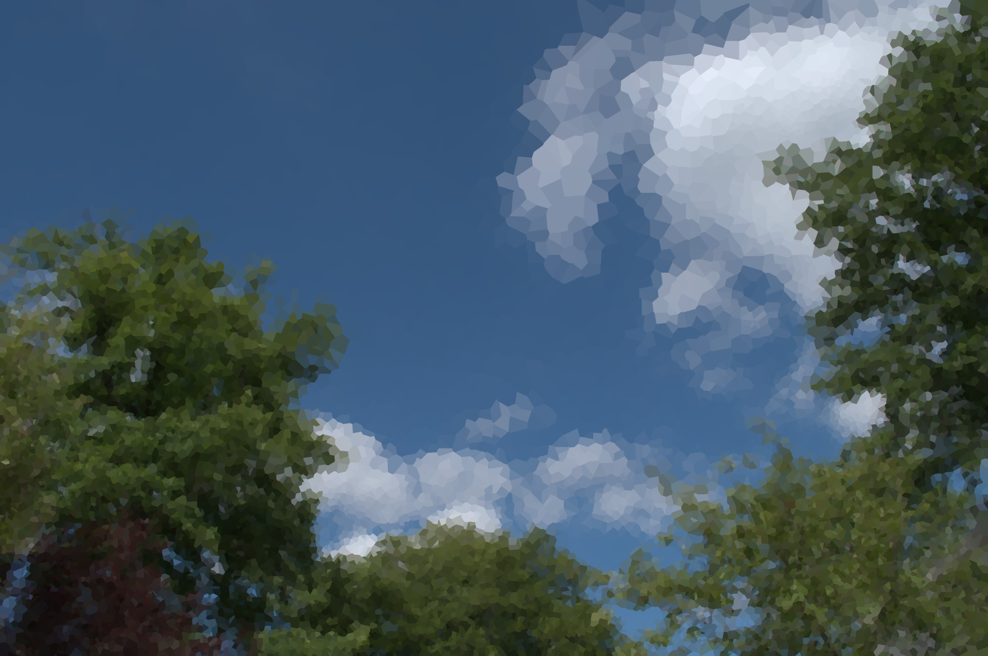
Actually I do want to recreate real cubist styles. I didn’t think that this rotated gradient square approach represents any cubist style I’ve seen before. The way I thought of it was that I’d use the contours of the existing image to generate segments and then transform images within them using warping.
Here’s an example which to me has almost everything that fits cubist style:
- Simplified lines, usually straight. I think we’ll need the Hough transform and its inverse, the second of which I don’t know how to implement.
- Multiple interwoven perspectives (transformations) of these lines (i.e. simple windows within which the transformations occur)
- Borders between each window.
If I didn’t have to rely on the stylize mega-script and I could choose how I wanted the image to be divided, the script would be really good. The whole 3D thing I was interested in can be part of that - again, my idea was to turn a stack of 2D images with the same dimensions into a single 3D image, screw it up and then take 2D slices of this image.
It’s really odd. When I changed it to i-0.25 there was some anti-aliasing, though quite low in quality. It turns out that the specification of the trilinearly-interpolated pixel is happening in the opposite direction from the currently-selected pixel so it’s really just blurring everything in a stupid way within 0.25 pixels, but if I turn it back to -i I’ve still got problems…
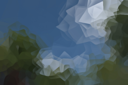
Weird. That’s the post-label segmented version of the original image which acts as a 3D map for all the label ids, and it’s used in the cubism() function within the final fill block. Without that, the function would return the result for label id 0 for a given input pixel. The entire image would be rotated as if it was within one big segment.
That was a vestigial text command which I was once using to check if one of the variables wasn’t being treated properly - the y and z offsets had gone mad because I assigned the x offset variable to them by mistake…
Anyway, the current code’s been modified again and this time I’ve bypassed cubism() altogether so that I’m only seeing what happens to the label ids.
The current code
#@gui Cubism: fx_jr_rep_cubism_preview
#@gui : sep = separator()
#@gui : 0. Recompute = button()
#@gui : 1. Threshold=float(2,0,15)
#@gui : 2. Smoothness=float(5,0,20)
#@gui : 3. X Offset Centre=float(0,-100,100)
#@gui : 4. X Offset Range=float(25,0,200)
#@gui : 5. Y Offset Centre=float(0,-100,100)
#@gui : 6. Y Offset Range=float(25,0,200)
#@gui : 7. Z Offset Centre=float(0,-100,100)
#@gui : 8. Z Offset Range=float(0,0,200)
#@gui : 9. Rot Angle Centre=float(0,-360,360)
#@gui : 10. Rot Angle Range=float(360,0,360)
#@gui : 11. Rot Axis X Centre=float(0,-1,1)
#@gui : 12. Rot Axis X Range=float(0,0,2)
#@gui : 13. Rot Axis Y Centre=float(0,-1,1)
#@gui : 14. Rot Axis Y Range=float(0,0,2)
#@gui : 15. Rot Axis Z Centre=float(1,-1,1)
#@gui : 16. Rot Axis Z Range=float(0,0,2)
#@gui : 17. AA Iterations=int(16,0,100)
#@gui : 18. Sharpness=float(0,0,2)
#@gui : 19. AA Anisotropy=float(1,0,1)
#@gui : 20. AA Gradient Smoothness=float(1,0,10)
#@gui : 21. Tensor Smoothness=float(5,0,10)
#@gui : 22. Time Step=float(15,5,50)


fx_jr_rep_cubism:
to_gray
# initial parameters for all images
rotac=$9
rotar=$10
rotxxc=$11
rotxxr=$12
rotxyc=$13
rotxyr=$14
rotxzc=$15
rotxzr=$16
aa=$17
repeat $! l[$>]
# initial parameters for each image
ww={w}
hh={h}
dd={d}
xoffc=$3*0.01*$ww
xoffr=$4*0.01*$hh
yoffc=$5*0.01*$dd
yoffr=$6*0.01*$ww
zoffc=$7*0.01*$hh
zoffr=$8*0.01*$dd
+b. $2% segment_watershed. $1	# embedded fx_segment_watershed
label.	# labelling the segments of the copied image
l[1]
# get the edges of the segment and find the distance to the nearest pixel on the other side of the nearest edge for each pixel in terms of x, y and z components
# this will be used for the anti-aliasing later on
+gradient_orientation. 3
a[^0] c
100%,100%,100%,1,"min(1,ceil(norm(I(#1))))"
rm[1]
distance. 1
+gradient_orientation. 3
f[1] "(i+0.5)"  # experimenting with this to find a good distance offset, should really be (i+0.5) for true distance to edge
a[1-4] c

endl
# uncomment this to blur this distance-to-edge image, was just another experiment but could be used to highlight the problem in a clearer way
# b. 2
# approximate the centre of each segment and store the x, y and z components in a new image which will store more parameters later
# this image's x coordinate is the segment id as specified in the labelled segment image (#1)
initsize={1+iM#1}
$initsize,10,1,1
vsize={$initsize*3}
eval ${-math_lib}"
coordinates_per_val=vector"$vsize"(0);
count_per_val=vector"$initsize"(0);
for(px=0,px<w#1,px++,
    for(py=0,py<h#1,py++,
		for(pz=0,pz<d#1,pz++,
			pos=i(#1,px,py,pz);
			coordinates_per_val[pos*3]+=px;
			coordinates_per_val[pos*3+1]+=py;
			coordinates_per_val[pos*3+2]+=pz;
			count_per_val[pos]++;
		);
    );
);
for(n=0,n<"$initsize",n++,
    coordinates_per_val[n*3]/=count_per_val[n];
    coordinates_per_val[n*3+1]/=count_per_val[n];
	coordinates_per_val[n*3+2]/=count_per_val[n];
	I(n,0)=coordinates_per_val[n*3];
	I(n,1)=coordinates_per_val[n*3+1];
	I(n,2)=coordinates_per_val[n*3+2];
);
"
# add pseudo-randomised parameters for each segment id to the parameters image
sh. 3,9,0,0 f. ">begin(randm=u(100,200);randa=u(1,3));srand((x+(randa)+(u))*(randm+y));u(-1,1)"
eval. "begin(multvec=["$xoffr","$yoffr","$zoffr","$rotar","$rotxxr","$rotxyr","$rotxzr"];
addvec=["$xoffc","$yoffc","$zoffc","$rotac","$rotxxc","$rotxyc","$rotxzc"]);
for(n=0,n<w,n++,
strip=crop(n,0,0,0,1,7,1,1);
draw(#4,(strip*multvec)+addvec,n,0,0,0,1,7,1,1,1))"
rm.
# get the edges, subtract a smoothed copy in order to create a mask for the anti-aliasing
+gradient_norm[1] f. "i>0?255:0"
+smooth. $aa,${18-22},0
-.. .
rm.
abs.
/. 255
# let's put all of this together now
f[0] "critical(begin(const spec=s;aa="$aa";
cubism(id,xx,yy,zz)=( # this function warps a given pixel using the parameters assigned to a specified id within the parameters image
params=crop(#3,id,0,0,0,1,10,1,1);
# get segment centre
xc=params[0];
yc=params[1];
zc=params[2];
# get offsets
xoff=params[3];
yoff=params[4];
zoff=params[5];
# get rotation angle and axis
ang=params[6];
xa=params[7];
ya=params[8];
za=params[9];
# rotate and offset
vx=xx-xc-xoff;
vy=yy-yc-yoff;
vz=zz-zc-zoff;
pix=[xa,ya,za];
select=(rot(asin(pix/norm(pix))*2/pi,ang)*[vx,vy,vz])+[xc,yc,zc];
# return the new pixel value
I(select,1,3)));
# anti-aliasing only if the setting's enabled and we're at a pixel where the mask (#4) has a non-zero value
(aa&&(i(#4)>0))?(
# get the displacements necessary to reach the nearest pixel on the other side of the nearest edge
dist=i(#2,x,y,z,0);
xdist=-i(#2,x,y,z,1)*dist;
ydist=-i(#2,x,y,z,2)*dist;
zdist=-i(#2,x,y,z,3)*dist;
# trilinear interpolation to determine the value of the nearest pixel behind the nearest edge
# we don't have to cubism() eight times for each pixel here since we can instead make a weighted histogram of ids
idlist=vector(#8,-1);
freqlist=vector(#8,0);
idnum=0;
xint=floor(xdist);yint=floor(ydist);zint=floor(zdist);
xo=xdist-xint;yo=ydist-yint;zo=zdist-zint;
gridmult=[(1-xo)*(1-yo)*(1-zo),xo*(1-yo)*(1-zo),(1-xo)*yo*(1-zo),xo*yo*(1-zo),(1-xo)*(1-yo)*zo,xo*(1-yo)*zo,(1-xo)*yo*zo,xo*yo*zo];
for(pz=0,pz<2,pz++,
	for(py=0,py<2,py++,
		for(px=0,px<2,px++,
			curr=i(#1,x+xint+px,y+yint+py,z+zint+pz,0,1,1);
			pos=find(idlist,curr);
			pos==-1?(idnum+=1;pos=find(idlist,-1);idlist[pos]=curr);
			freqlist[pos]+=gridmult[pz*4+py*2+px];
		);
	);
);
val=0; # val=vector(#spec,0);
for(n=0,n<idnum,n++,
# construct the final value for the interpolated pixel
val+=idlist[n]*freqlist[n]);
# interpolate between that pixel and the current one in accordance with the AA mask
lerp(val,i(#1,x,y,z,0,1,1),i(#4))):
# if we don't need any AA, we can just use the current pixel
(i(#1,x,y,z,0,1,1)))
"
# clean up now that we're done
display
rm[^0]
endl done
to_rgb
n 0,255
fx_jr_rep_cubism_preview:
fx_jr_rep_cubism ${2-23}


,_oil_on_canvas,_81.3_x_61_cm,_Smart_Museum_of_Art.jpg)