Attempt at cubism

Okay. Here’s the code right now:

#@gui Cubism: fx_jr_rep_cubism_preview
#@gui : sep = separator()
#@gui : 0. Recompute = button()
#@gui : 1. Threshold=float(2,0,15)
#@gui : 2. Smoothness=float(5,0,20)
#@gui : 3. Offset Amplitude=float(10,0,100)
#@gui : 4. X Offset Centre=float(0,-100,100)
#@gui : 5. X Offset Range=float(25,0,200)
#@gui : 6. Y Offset Centre=float(0,-100,100)
#@gui : 7. Y Offset Range=float(25,0,200)
#@gui : 8. Z Offset Centre=float(0,-100,100)
#@gui : 9. Z Offset Range=float(0,0,200)
#@gui : 10. Rot Angle Centre=float(0,-360,360)
#@gui : 11. Rot Angle Range=float(360,0,360)
#@gui : 12. Rot Axis X Centre=float(0,-1,1)
#@gui : 13. Rot Axis X Range=float(0,0,2)
#@gui : 14. Rot Axis Y Centre=float(0,-1,1)
#@gui : 15. Rot Axis Y Range=float(0,0,2)
#@gui : 16. Rot Axis Z Centre=float(1,-1,1)
#@gui : 17. Rot Axis Z Range=float(0,0,2)
#@gui : 18. AA Iterations=int(16,0,100)
#@gui : 19. Time Step=float(16,5,50)

fx_jr_rep_cubism:
# initial parameters for all images
rotac=$10
rotar=$11
rotxxc=$12
rotxxr=$13
rotxyc=$14
rotxyr=$15
rotxzc=$16
rotxzr=$17
aa=$18
repeat $! l[$>]
# initial parameters for each image
ww={w}
hh={h}
dd={d}
xoffc=$4*0.01*$ww
xoffr=$5*0.01*$hh
yoffc=$6*0.01*$dd
yoffr=$7*0.01*$ww
zoffc=$8*0.01*$hh
zoffr=$9*0.01*$dd
amp={$3*norm(w,h,d)*0.01}
+b. $2% segment_watershed. $1	# embedded fx_segment_watershed
label.	# labelling the segments of the copied image
l[1]
# get the edges of the segment and find the distance to the nearest pixel on the other side of the nearest edge for each pixel in terms of x, y and z components
# this will be used for the anti-aliasing later on
+gradient_orientation. 3
a[^0] c
100%,100%,100%,1,"min(1,ceil(norm(I(#1))))"
rm[1]
distance. 1
+gradient_orientation. 3
f[1] "-(i+1)" # experimenting with this to find a good distance offset, should really be -(i+0.5) for true distance to edge
*[2-4] [1] a[2-4] c
rm[1]
endl
# uncomment this to blur this distance-to-edge image, was just another experiment but could be used to highlight the problem in a clearer way
#b. 2
# approximate the centre of each segment and store the x, y and z components in a new image which will store more parameters later
# this image's x coordinate is the segment id as specified in the labelled segment image (#1)
initsize={1+iM#1}
$initsize,10,1,1
vsize={$initsize*3}
eval ${-math_lib}"
coordinates_per_val=vector"$vsize"(0);
count_per_val=vector"$initsize"(0);
for(px=0,px<w#1,px++,
    for(py=0,py<h#1,py++,
		for(pz=0,pz<d#1,pz++,
			pos=i(#1,px,py,pz);
			coordinates_per_val[pos*3]+=px;
			coordinates_per_val[pos*3+1]+=py;
			coordinates_per_val[pos*3+2]+=pz;
			count_per_val[pos]++;
		);
    );
);
for(n=0,n<"$initsize",n++,
    coordinates_per_val[n*3]/=count_per_val[n];
    coordinates_per_val[n*3+1]/=count_per_val[n];
	coordinates_per_val[n*3+2]/=count_per_val[n];
	I(n,0)=coordinates_per_val[n*3];
	I(n,1)=coordinates_per_val[n*3+1];
	I(n,2)=coordinates_per_val[n*3+2];
);
"
# add pseudo-randomised parameters for each segment id to the parameters image
sh. 3,9,0,0 f. ">begin(randm=u(100,200);randa=u(1,3));srand((x+(randa)+(u))*(randm+y));u(-1,1)"
eval. "begin(multvec=["$xoffr","$yoffr","$zoffr","$rotar","$rotxxr","$rotxyr","$rotxzr"];
addvec=["$xoffc","$yoffc","$zoffc","$rotac","$rotxxc","$rotxyc","$rotxzc"]);
for(n=0,n<w,n++,
strip=crop(n,0,0,0,1,7,1,1);
draw(#4,strip*multvec+addvec,n,0,0,0,1,7,1,1,1))"
rm.
# get the edges, subtract a smoothed copy in order to create a mask for the anti-aliasing
+gradient_norm[1] f. "i>0?255:0"
+meancurvature_flow. $aa,$19
-.. .
rm.
abs.
/. 255
# let's put all of this together now
f[0] "begin(const spec=s;aa="$aa";
cubism(id,xx,yy,zz)=( # this function warps a given pixel using the parameters assigned to a specified id within the parameters image
params=crop(#3,id,0,0,0,1,10,1,1);
xoff=params[0]+params[3];
yoff=params[1]+params[4];
zoff=params[2]+params[5];
ang=params[6];
xa=params[7];
ya=params[8];
za=params[9];
vx=xx-xoff;
vy=yy-yoff;
vz=zz-zoff;
pix=[xa,ya,za];
select=rot(asin(pix/norm(pix))*2/pi,ang)*[vx,vy,vz]+[xoff,yoff,zoff];
I(select,1,3)));
# anti-aliasing only if the setting's enabled and we're at a pixel where the mask (#4) has a non-zero value
(aa&&(i(#4)>0))?(
# get the displacements necessary to reach the nearest pixel on the other side of the nearest edge
xs=i(#2,x,y,z,0);
ys=i(#2,x,y,z,1);
zs=i(#2,x,y,z,2);
# trilinear interpolation to determine the value of the nearest pixel behind the nearest edge
# we don't have to cubism() eight times for each pixel here since we can instead make a weighted histogram of ids
idlist=vector(#8,-1);
freqlist=vector(#8,0);
idnum=0;
xint=floor(xs);yint=floor(ys);zint=floor(zs);
xo=xs-xint;yo=ys-yint;zo=zs-zint;
gridmult=[(1-xo)*(1-yo)*(1-zo),xo*(1-yo)*(1-zo),(1-xo)*yo*(1-zo),xo*yo*(1-zo),(1-xo)*(1-yo)*zo,xo*(1-yo)*zo,(1-xo)*yo*zo,xo*yo*zo];
for(pz=0,pz<2,pz++,
	for(py=0,py<2,py++,
		for(px=0,px<2,px++,
			curr=i(#1,x+xint+px,y+yint+py,z+zint+pz,0,1,1);
			pos=find(idlist,curr);
			pos==-1?(idnum+=1;pos=find(idlist,-1);idlist[pos]=curr);
			freqlist[pos]+=gridmult[pz*4+py*2+px];
		);
	);
);
val=vector(#spec,0);
for(n=0,n<idnum,n++,
# construct the final value for the interpolated pixel
val+=cubism(idlist[n],x,y,z)*freqlist[n]);
# interpolate between that pixel and the current one in accordance with the AA mask
lerp(val,cubism(i(#1,x,y,z,0,1,1),x,y,z),i(#4))):
# if we don't need any AA, we can just use the current pixel
(cubism(i(#1,x,y,z,0,1,1),x,y,z))
"
# clean up now that we're done
rm[^0]
endl done
fx_jr_rep_cubism_preview:
fx_jr_rep_cubism ${2-20}

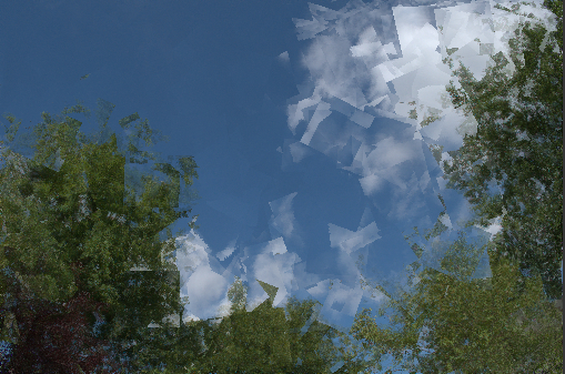
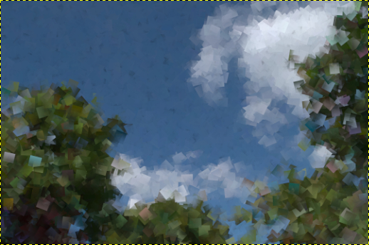
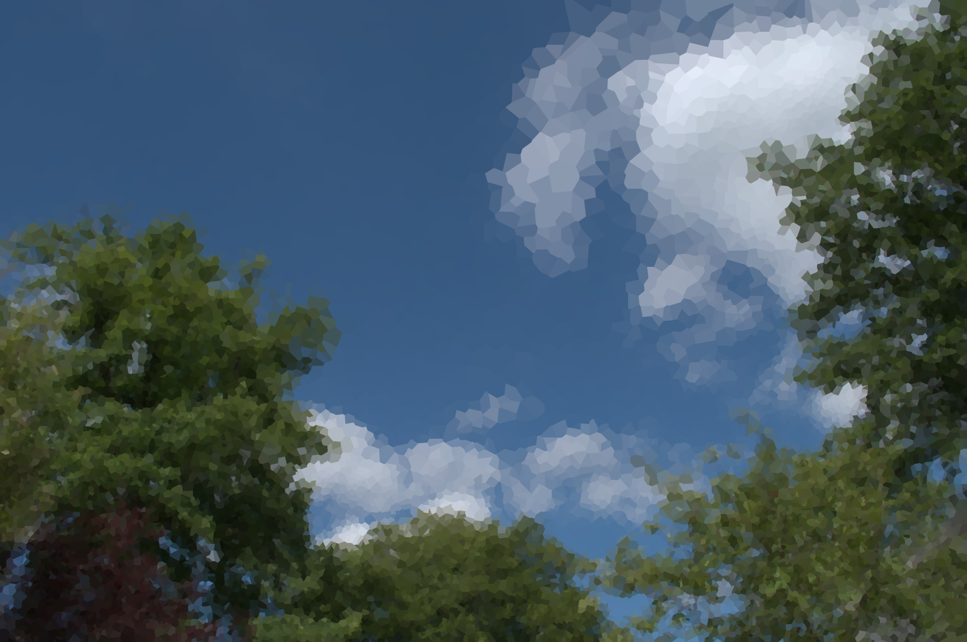
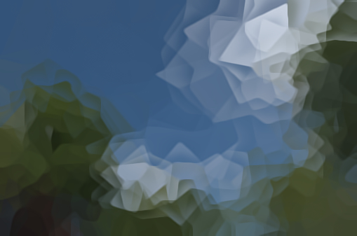
…and here’s what it does:

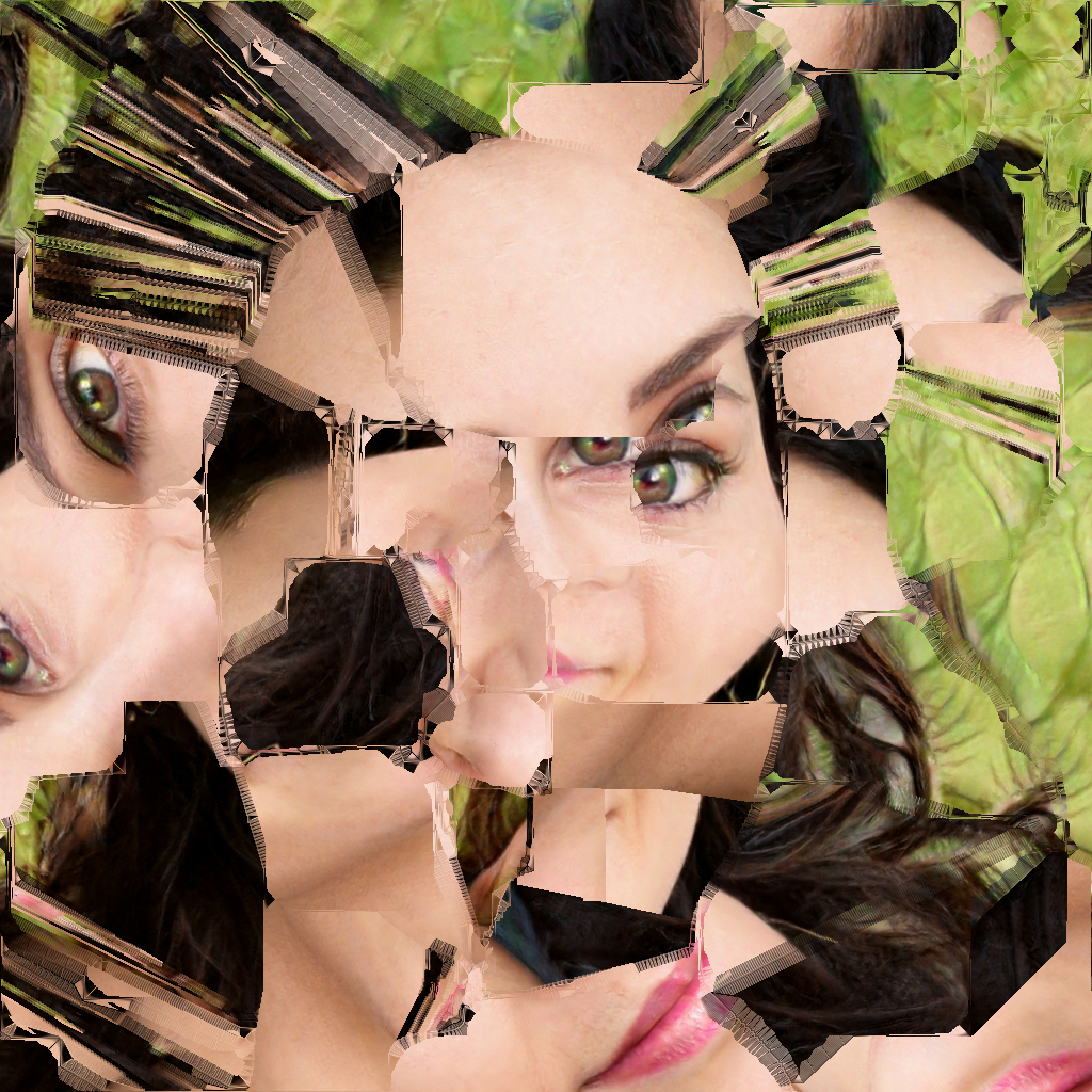
The way I describe it is that the smoothing is at right-angles to the edges! I don’t know how to deal with this at all.

Maybe disable multithreading within f block? That solved a bug I found when the code looks good.

The question is, where in the code does the anti-aliasing happen? My guess is after rotation, after which we would have to smooth the edge, or rotate an up-sized piece and then downsize to make the stair-casing fuzzier, choosing the appropriate interpolation.

Is the zippering also an artifact? Would that have to do with your attempt at smoothing an aliased edge?

Now that you mention it, I really like the zipper effect.

I like it too but it’s a little unpredictable and may not be suitable for cubism.

@Reptorian That doesn’t work, same output.

@afre The AA happens after the rotations. It shouldn’t really matter because the segments aren’t being rotated - rather, the segments are like windows within which the image is being transformed. All the AA really involves is finding out what would happen to each pixel for a given set of ids and blending the results.

The zipper effects are the problem, and this is what I meant when I was talking about the AA happening at right-angles to the edges - it’s like parts of the edges for the gradual blending have been flipped!

Also, if I change

f[1] "-(i+1)" # experimenting with this to find a good distance offset, should really be -(i+0.5) for true distance to edge

…to:

f[1] "-(i)" # experimenting with this to find a good distance offset, should really be -(i+0.5) for true distance to edge

…the AA stops happening.

Hmm, what if you remove the minus sign? Guessing here.

Calling it AA confused the heck out of me until you confirmed that it was the zipper effect I coined. In the resultant image, I see AA where zipper isn’t. They are two separate problems; related perhaps but different.

If I omit that altogether, the result is much better. The AA is more apparent though.


Remarks

I would suggest that we stop the randomization while debugging. That is the only way one could make comparisons between code changes. Also, try preventing too many narrow strips. I noticed that they are very common and usually clustered together.

I had to sort out a few other things with this command.

The command right now
#@gui Cubism: fx_jr_rep_cubism_preview
#@gui : sep = separator()
#@gui : 0. Recompute = button()
#@gui : 1. Threshold=float(2,0,15)
#@gui : 2. Smoothness=float(5,0,20)
#@gui : 3. X Offset Centre=float(0,-100,100)
#@gui : 4. X Offset Range=float(25,0,200)
#@gui : 5. Y Offset Centre=float(0,-100,100)
#@gui : 6. Y Offset Range=float(25,0,200)
#@gui : 7. Z Offset Centre=float(0,-100,100)
#@gui : 8. Z Offset Range=float(0,0,200)
#@gui : 9. Rot Angle Centre=float(0,-360,360)
#@gui : 10. Rot Angle Range=float(360,0,360)
#@gui : 11. Rot Axis X Centre=float(0,-1,1)
#@gui : 12. Rot Axis X Range=float(0,0,2)
#@gui : 13. Rot Axis Y Centre=float(0,-1,1)
#@gui : 14. Rot Axis Y Range=float(0,0,2)
#@gui : 15. Rot Axis Z Centre=float(1,-1,1)
#@gui : 16. Rot Axis Z Range=float(0,0,2)
#@gui : 17. AA Iterations=int(16,0,100)
#@gui : 18. Time Step=float(16,5,50)

fx_jr_rep_cubism:
# initial parameters for all images
rotac=$9
rotar=$10
rotxxc=$11
rotxxr=$12
rotxyc=$13
rotxyr=$14
rotxzc=$15
rotxzr=$16
aa=$17
ts=$18
repeat $! l[$>]
# initial parameters for each image
ww={w}
hh={h}
dd={d}
xoffc=$3*0.01*$ww
xoffr=$4*0.01*$hh
yoffc=$5*0.01*$dd
yoffr=$6*0.01*$ww
zoffc=$7*0.01*$hh
zoffr=$8*0.01*$dd
+b. $2% segment_watershed. $1	# embedded fx_segment_watershed
label.	# labelling the segments of the copied image
l[1]
# get the edges of the segment and find the distance to the nearest pixel on the other side of the nearest edge for each pixel in terms of x, y and z components
# this will be used for the anti-aliasing later on
+gradient_orientation. 3
a[^0] c
100%,100%,100%,1,"min(1,ceil(norm(I(#1))))"
rm[1]
distance. 1
+gradient_orientation. 3
#f[1] "(i)"  experimenting with this to find a good distance offset, should really be -(i+0.5) for true distance to edge
*[2-4] [1] a[2-4] c
rm[1]
endl
# uncomment this to blur this distance-to-edge image, was just another experiment but could be used to highlight the problem in a clearer way
# b. 2
# approximate the centre of each segment and store the x, y and z components in a new image which will store more parameters later
# this image's x coordinate is the segment id as specified in the labelled segment image (#1)
initsize={1+iM#1}
$initsize,10,1,1
vsize={$initsize*3}
eval ${-math_lib}"
coordinates_per_val=vector"$vsize"(0);
count_per_val=vector"$initsize"(0);
for(px=0,px<w#1,px++,
    for(py=0,py<h#1,py++,
		for(pz=0,pz<d#1,pz++,
			pos=i(#1,px,py,pz);
			coordinates_per_val[pos*3]+=px;
			coordinates_per_val[pos*3+1]+=py;
			coordinates_per_val[pos*3+2]+=pz;
			count_per_val[pos]++;
		);
    );
);
for(n=0,n<"$initsize",n++,
    coordinates_per_val[n*3]/=count_per_val[n];
    coordinates_per_val[n*3+1]/=count_per_val[n];
	coordinates_per_val[n*3+2]/=count_per_val[n];
	I(n,0)=coordinates_per_val[n*3];
	I(n,1)=coordinates_per_val[n*3+1];
	I(n,2)=coordinates_per_val[n*3+2];
);
"
# add pseudo-randomised parameters for each segment id to the parameters image
sh. 3,9,0,0 f. ">begin(randm=u(100,200);randa=u(1,3));srand((x+(randa)+(u))*(randm+y));u(-1,1)"
eval. "begin(multvec=["$xoffr","$yoffr","$zoffr","$rotar","$rotxxr","$rotxyr","$rotxzr"];
addvec=["$xoffc","$yoffc","$zoffc","$rotac","$rotxxc","$rotxyc","$rotxzc"]);
for(n=0,n<w,n++,
strip=crop(n,0,0,0,1,7,1,1);
draw(#4,(strip*multvec)+addvec,n,0,0,0,1,7,1,1,1))"
rm.
# get the edges, subtract a smoothed copy in order to create a mask for the anti-aliasing
+gradient_norm[1] f. "i>0?255:0"
+meancurvature_flow. $aa,$ts
-.. .
rm.
abs.
/. 255
display
# let's put all of this together now
f[0] "critical(begin(const spec=s;aa="$aa";
cubism(id,xx,yy,zz)=( # this function warps a given pixel using the parameters assigned to a specified id within the parameters image
params=crop(#3,id,0,0,0,1,10,1,1);
# get segment centre
xc=params[0];
yc=params[1];
zc=params[2];
# get offsets
xoff=params[3];
yoff=params[4];
zoff=params[5];
# get rotation angle and axis
ang=params[6];
xa=params[7];
ya=params[8];
za=params[9];
# rotate and offset
vx=xx-xc-xoff;
vy=yy-yc-yoff;
vz=zz-zc-zoff;
pix=[xa,ya,za];
select=(rot(asin(pix/norm(pix))*2/pi,ang)*[vx,vy,vz])+[xc,yc,zc];
# return the new pixel value
I(select,1,3)));
# anti-aliasing only if the setting's enabled and we're at a pixel where the mask (#4) has a non-zero value
(aa&&(i(#4)>0))?(
# get the displacements necessary to reach the nearest pixel on the other side of the nearest edge
xs=i(#2,x,y,z,0);
ys=i(#2,x,y,z,1);
zs=i(#2,x,y,z,2);
# trilinear interpolation to determine the value of the nearest pixel behind the nearest edge
# we don't have to cubism() eight times for each pixel here since we can instead make a weighted histogram of ids
idlist=vector(#8,-1);
freqlist=vector(#8,0);
idnum=0;
xint=floor(xs);yint=floor(ys);zint=floor(zs);
xo=xs-xint;yo=ys-yint;zo=zs-zint;
gridmult=[(1-xo)*(1-yo)*(1-zo),xo*(1-yo)*(1-zo),(1-xo)*yo*(1-zo),xo*yo*(1-zo),(1-xo)*(1-yo)*zo,xo*(1-yo)*zo,(1-xo)*yo*zo,xo*yo*zo];
for(pz=0,pz<2,pz++,
	for(py=0,py<2,py++,
		for(px=0,px<2,px++,
			curr=i(#1,x+xint+px,y+yint+py,z+zint+pz,0,1,1);
			pos=find(idlist,curr);
			pos==-1?(idnum+=1;pos=find(idlist,-1);idlist[pos]=curr);
			freqlist[pos]+=gridmult[pz*4+py*2+px];
		);
	);
);
val=vector(#spec,0);
for(n=0,n<idnum,n++,
# construct the final value for the interpolated pixel
val+=cubism(idlist[n],x,y,z)*freqlist[n]);
# interpolate between that pixel and the current one in accordance with the AA mask
lerp(val,cubism(i(#1,x,y,z,0,1,1),x,y,z),-i(#4))):
# if we don't need any AA, we can just use the current pixel
(cubism(i(#1,x,y,z,0,1,1),x,y,z)))
"
# clean up now that we're done
rm[^0]
endl done
text {$zoffc}
fx_jr_rep_cubism_preview:
fx_jr_rep_cubism ${2-19}

Commenting out the entire line doesn’t do anything though.

Easily done, the randomisation for everything can be set to 0.

That’s down to the segmentation not reacting well to the blurring. I don’t see any alternatives for generating patches based on the shape of the original image besides the cutout script.

Weird, because for me it removed all of the zipper effects, and a small amount of aliasing between the narrow pieces.

What segmentation techniques have you tried? Would it be possible to reject narrow pieces within your current method?

Which line did you omit? We might not be talking about the same one…

I have only tried segment_watershed. I have found slic but I’d need to extend it to 3 dimensions. segment_snake and segment_cells don’t produce the kinds of patches I want; they conform to image contours far too much and leave huge backgrounds.

This one, which you also did in your latest version.


Latest version

1 After display, if I do f[2] 0, the resultant image doesn’t look very different without [2], using your default parameters.

2 Typo: your image has a 0 at the top left corner in the plugin preview.

3 David’s and GIMP’s cubism are very different from yours. They maintain the basic structure of the original image.

Raw from @Carmelo_DrRaw.

image

David’s (default)

image

GIMP’s (50,2.5)

image

PS
The challenge is to do something in between their cubism and yours, and somehow make it more deliberate instead of a mere collection of random haphazard shapes. Your intent probably isn’t to replicate real cubism; consider this food for thought or a challenge.

Actually I do want to recreate real cubist styles. I didn’t think that this rotated gradient square approach represents any cubist style I’ve seen before. The way I thought of it was that I’d use the contours of the existing image to generate segments and then transform images within them using warping.

Here’s an example which to me has almost everything that fits cubist style:

https://en.wikipedia.org/wiki/File:Jean_Metzinger,1915,Soldat_jouant_aux%C3%A9checs(Soldier_at_a_Game_of_Chess),_oil_on_canvas,_81.3_x_61_cm,_Smart_Museum_of_Art.jpg

  1. Simplified lines, usually straight. I think we’ll need the Hough transform and its inverse, the second of which I don’t know how to implement.
  2. Multiple interwoven perspectives (transformations) of these lines (i.e. simple windows within which the transformations occur)
  3. Borders between each window.

If I didn’t have to rely on the stylize mega-script and I could choose how I wanted the image to be divided, the script would be really good. The whole 3D thing I was interested in can be part of that - again, my idea was to turn a stack of 2D images with the same dimensions into a single 3D image, screw it up and then take 2D slices of this image.

It’s really odd. When I changed it to i-0.25 there was some anti-aliasing, though quite low in quality. It turns out that the specification of the trilinearly-interpolated pixel is happening in the opposite direction from the currently-selected pixel so it’s really just blurring everything in a stupid way within 0.25 pixels, but if I turn it back to -i I’ve still got problems…

Weird. That’s the post-label segmented version of the original image which acts as a 3D map for all the label ids, and it’s used in the cubism() function within the final fill block. Without that, the function would return the result for label id 0 for a given input pixel. The entire image would be rotated as if it was within one big segment.

That was a vestigial text command which I was once using to check if one of the variables wasn’t being treated properly - the y and z offsets had gone mad because I assigned the x offset variable to them by mistake…

Anyway, the current code’s been modified again and this time I’ve bypassed cubism() altogether so that I’m only seeing what happens to the label ids.

The current code
#@gui Cubism: fx_jr_rep_cubism_preview
#@gui : sep = separator()
#@gui : 0. Recompute = button()
#@gui : 1. Threshold=float(2,0,15)
#@gui : 2. Smoothness=float(5,0,20)
#@gui : 3. X Offset Centre=float(0,-100,100)
#@gui : 4. X Offset Range=float(25,0,200)
#@gui : 5. Y Offset Centre=float(0,-100,100)
#@gui : 6. Y Offset Range=float(25,0,200)
#@gui : 7. Z Offset Centre=float(0,-100,100)
#@gui : 8. Z Offset Range=float(0,0,200)
#@gui : 9. Rot Angle Centre=float(0,-360,360)
#@gui : 10. Rot Angle Range=float(360,0,360)
#@gui : 11. Rot Axis X Centre=float(0,-1,1)
#@gui : 12. Rot Axis X Range=float(0,0,2)
#@gui : 13. Rot Axis Y Centre=float(0,-1,1)
#@gui : 14. Rot Axis Y Range=float(0,0,2)
#@gui : 15. Rot Axis Z Centre=float(1,-1,1)
#@gui : 16. Rot Axis Z Range=float(0,0,2)
#@gui : 17. AA Iterations=int(16,0,100)
#@gui : 18. Sharpness=float(0,0,2)
#@gui : 19. AA Anisotropy=float(1,0,1)
#@gui : 20. AA Gradient Smoothness=float(1,0,10)
#@gui : 21. Tensor Smoothness=float(5,0,10)
#@gui : 22. Time Step=float(15,5,50)


fx_jr_rep_cubism:
to_gray
# initial parameters for all images
rotac=$9
rotar=$10
rotxxc=$11
rotxxr=$12
rotxyc=$13
rotxyr=$14
rotxzc=$15
rotxzr=$16
aa=$17
repeat $! l[$>]
# initial parameters for each image
ww={w}
hh={h}
dd={d}
xoffc=$3*0.01*$ww
xoffr=$4*0.01*$hh
yoffc=$5*0.01*$dd
yoffr=$6*0.01*$ww
zoffc=$7*0.01*$hh
zoffr=$8*0.01*$dd
+b. $2% segment_watershed. $1	# embedded fx_segment_watershed
label.	# labelling the segments of the copied image
l[1]
# get the edges of the segment and find the distance to the nearest pixel on the other side of the nearest edge for each pixel in terms of x, y and z components
# this will be used for the anti-aliasing later on
+gradient_orientation. 3
a[^0] c
100%,100%,100%,1,"min(1,ceil(norm(I(#1))))"
rm[1]
distance. 1
+gradient_orientation. 3
f[1] "(i+0.5)"  # experimenting with this to find a good distance offset, should really be (i+0.5) for true distance to edge
a[1-4] c

endl
# uncomment this to blur this distance-to-edge image, was just another experiment but could be used to highlight the problem in a clearer way
# b. 2
# approximate the centre of each segment and store the x, y and z components in a new image which will store more parameters later
# this image's x coordinate is the segment id as specified in the labelled segment image (#1)
initsize={1+iM#1}
$initsize,10,1,1
vsize={$initsize*3}
eval ${-math_lib}"
coordinates_per_val=vector"$vsize"(0);
count_per_val=vector"$initsize"(0);
for(px=0,px<w#1,px++,
    for(py=0,py<h#1,py++,
		for(pz=0,pz<d#1,pz++,
			pos=i(#1,px,py,pz);
			coordinates_per_val[pos*3]+=px;
			coordinates_per_val[pos*3+1]+=py;
			coordinates_per_val[pos*3+2]+=pz;
			count_per_val[pos]++;
		);
    );
);
for(n=0,n<"$initsize",n++,
    coordinates_per_val[n*3]/=count_per_val[n];
    coordinates_per_val[n*3+1]/=count_per_val[n];
	coordinates_per_val[n*3+2]/=count_per_val[n];
	I(n,0)=coordinates_per_val[n*3];
	I(n,1)=coordinates_per_val[n*3+1];
	I(n,2)=coordinates_per_val[n*3+2];
);
"
# add pseudo-randomised parameters for each segment id to the parameters image
sh. 3,9,0,0 f. ">begin(randm=u(100,200);randa=u(1,3));srand((x+(randa)+(u))*(randm+y));u(-1,1)"
eval. "begin(multvec=["$xoffr","$yoffr","$zoffr","$rotar","$rotxxr","$rotxyr","$rotxzr"];
addvec=["$xoffc","$yoffc","$zoffc","$rotac","$rotxxc","$rotxyc","$rotxzc"]);
for(n=0,n<w,n++,
strip=crop(n,0,0,0,1,7,1,1);
draw(#4,(strip*multvec)+addvec,n,0,0,0,1,7,1,1,1))"
rm.
# get the edges, subtract a smoothed copy in order to create a mask for the anti-aliasing
+gradient_norm[1] f. "i>0?255:0"
+smooth. $aa,${18-22},0
-.. .
rm.
abs.
/. 255
# let's put all of this together now
f[0] "critical(begin(const spec=s;aa="$aa";
cubism(id,xx,yy,zz)=( # this function warps a given pixel using the parameters assigned to a specified id within the parameters image
params=crop(#3,id,0,0,0,1,10,1,1);
# get segment centre
xc=params[0];
yc=params[1];
zc=params[2];
# get offsets
xoff=params[3];
yoff=params[4];
zoff=params[5];
# get rotation angle and axis
ang=params[6];
xa=params[7];
ya=params[8];
za=params[9];
# rotate and offset
vx=xx-xc-xoff;
vy=yy-yc-yoff;
vz=zz-zc-zoff;
pix=[xa,ya,za];
select=(rot(asin(pix/norm(pix))*2/pi,ang)*[vx,vy,vz])+[xc,yc,zc];
# return the new pixel value
I(select,1,3)));
# anti-aliasing only if the setting's enabled and we're at a pixel where the mask (#4) has a non-zero value
(aa&&(i(#4)>0))?(
# get the displacements necessary to reach the nearest pixel on the other side of the nearest edge
dist=i(#2,x,y,z,0);
xdist=-i(#2,x,y,z,1)*dist;
ydist=-i(#2,x,y,z,2)*dist;
zdist=-i(#2,x,y,z,3)*dist;
# trilinear interpolation to determine the value of the nearest pixel behind the nearest edge
# we don't have to cubism() eight times for each pixel here since we can instead make a weighted histogram of ids
idlist=vector(#8,-1);
freqlist=vector(#8,0);
idnum=0;
xint=floor(xdist);yint=floor(ydist);zint=floor(zdist);
xo=xdist-xint;yo=ydist-yint;zo=zdist-zint;
gridmult=[(1-xo)*(1-yo)*(1-zo),xo*(1-yo)*(1-zo),(1-xo)*yo*(1-zo),xo*yo*(1-zo),(1-xo)*(1-yo)*zo,xo*(1-yo)*zo,(1-xo)*yo*zo,xo*yo*zo];
for(pz=0,pz<2,pz++,
	for(py=0,py<2,py++,
		for(px=0,px<2,px++,
			curr=i(#1,x+xint+px,y+yint+py,z+zint+pz,0,1,1);
			pos=find(idlist,curr);
			pos==-1?(idnum+=1;pos=find(idlist,-1);idlist[pos]=curr);
			freqlist[pos]+=gridmult[pz*4+py*2+px];
		);
	);
);
val=0; # val=vector(#spec,0);
for(n=0,n<idnum,n++,
# construct the final value for the interpolated pixel
val+=idlist[n]*freqlist[n]);
# interpolate between that pixel and the current one in accordance with the AA mask
lerp(val,i(#1,x,y,z,0,1,1),i(#4))):
# if we don't need any AA, we can just use the current pixel
(i(#1,x,y,z,0,1,1)))
"
# clean up now that we're done
display
rm[^0]
endl done
to_rgb
n 0,255
fx_jr_rep_cubism_preview:
fx_jr_rep_cubism ${2-23}

What I am saying is that yours doesn’t look like cubism either and that the truth lies somewhere between yours and theirs. Look: do any of these intermediaries of your cubism resemble the landscape image that I posted above? I am not convinced.

[2] kind of has the same flat area as the cloudless region of the sky but that is it. In fact, upon closer inspection, I now know the cause of the zippering and narrow pieces: the flat and low textured areas.

I completely ignored that. Yeah, it doesn’t really look like real cubism that much now that I think about it. If anything the Rodilius script is closer to that, though I don’t think that keeping the same structure is so necessary for cubism…

Yes, I can see that now! I’m not sure why segment_watershed does this…

Try the pattern → mosaic filter for g’mic-qt. See if you like the structure. That may be the solution.

1 Like

You are a genius, I have no idea why I didn’t think of that!

Here’s what I’ve come up with:

jr_mosaic 20,15,10%

jr_mosaic:
repeat $! l[$>]
+gradient_norm b. $3 n. 0,1 
100%,100%,100%,2,'u<0.25*(lerp($1%,i(#1),$2%))^4?[u,1]' s. c
distance. 1 *. -1  watershed.. . rm[1,3]
blend shapeaverage
endl
done

The second and third options allow the size of the segments to adjust to the level of detail in the original image.

1 Like

I like the simpler code. If you could combine the chunks to make more deliberate intersecting shapes, and chose more primary, complimentary and opponent colours; then you would be done. :stuck_out_tongue:

Hold on, the borders of those mosaic pieces in that image are smooth! How did you do that? Was that with a post-processing anti-aliasing thing?

Anyway, I now have two filters to sort out then: the cubism one and the previous jumbling thing. One of the ideas I have for the new cubism mosaic thing involves using gradients within each segment. I should also generate some edges…

So here’s something I made from that:

#@gui Multi-Mosaic: fx_jr_multi_mosaic_preview
#@gui : sep = separator()
#@gui : 0. Recompute = button()
#@gui : 1. Iterations=int(3,1,10)
#@gui : sep = separator(), note = note("<small><b>Mosaic</b></small>")
#@gui : 2. Density=float(15,0,100)
#@gui : 3. Details Influence=float(15,0,100)
#@gui : 4. Details Smoothness=float(0,0,100)
#@gui : sep = separator(), note = note("<small><b>Smooth [Diffusion]</b></small>")
#@gui : 5. Iterations=int(16,0,100)
#@gui : 6. Sharpness=float(0.5,0,2)
#@gui : 7. Anisotropy=float(1,0,1)
#@gui : 8. Gradient Smoothness=float(3,0,10)
#@gui : 9. Tensor Smoothness=float(5,0,10)
#@gui : 10. Time Step=float(15,5,50)
#@gui : sep = separator(), note = note("<small><b>Edges [Gradient Norm]</b></small>")
#@gui : 11. Opacity=float(1,0,1)
#@gui : 12. Smoothness=float(0,0,10)
#@gui : 13. Linearity=float(0.5,0,1.5)
#@gui : 14. Min Threshold=float(0,0,100)
#@gui : 15. Max Threshold=float(100,0,100)
#@gui : 16. Negative Colors=bool(0)
#@gui : sep = separator(), note = note("<small><b>Final Edge Blend</b></small>")
#@gui : 17. Edge Blend=bool(1)
#@gui : 18. Smoothness=float(15,0,100)

fx_jr_multi_mosaic:
repeat $! l[$>]
repeat $1 +l[0]
+gradient_norm n. 0,1 b. $4 
100%,100%,100%,2,'u<0.25*(lerp($2%,i(#1),$3%))^(4)?[u,1]' s. c
distance. 1 *. -1  watershed.. . rm[1,3]
blend shapeaverage
smooth. ${5-10},0
+fx_gradient_norm ${12-16} *. $11
split_opacity..
-[^1]
a c
endl done
rm[0]
if $17 blend_edges $18 fi
endl done

fx_jr_multi_mosaic_preview :
fx_jr_multi_mosaic ${2-19}

fx_jr_multi_mosaic 3,31.3,42.7,0,20,0.594,1,1.73,3.25,7.925,0,0,0.5,0,100,0,1,8 on this image:

…gives me this:

image

Edit: a few changes. Now it can do multiple densities at once.

New script
#@gui Multi-Mosaic: fx_jr_multi_mosaic_preview
#@gui : sep = separator()
#@gui : 0. Recompute = button()
#@gui : 1. Iterations=int(3,1,10)
#@gui : sep = separator(), note = note("<small><b>Mosaic</b></small>")
#@gui : 2. Lowest Density=float(15,0,100)
#@gui : 3. Highest Density=float(45,0,100)
#@gui : 4. Details Influence=float(50,0,100)
#@gui : 5. Details Smoothness=float(0,0,100)
#@gui : sep = separator(), note = note("<small><b>Smooth [Diffusion]</b></small>")
#@gui : 6. Iterations=int(16,0,100)
#@gui : 7. Sharpness=float(0.5,0,2)
#@gui : 8. Anisotropy=float(1,0,1)
#@gui : 10. Gradient Smoothness=float(3,0,10)
#@gui : 11. Tensor Smoothness=float(5,0,10)
#@gui : 12. Time Step=float(15,5,50)
#@gui : sep = separator(), note = note("<small><b>Edges [Gradient Norm]</b></small>")
#@gui : 13. Opacity=float(1,0,1)
#@gui : 14. Smoothness=float(0,0,10)
#@gui : 15. Linearity=float(0.5,0,1.5)
#@gui : 16. Min Threshold=float(0,0,100)
#@gui : 17. Max Threshold=float(100,0,100)
#@gui : 18. Negative Colors=bool(0)
#@gui : sep = separator(), note = note("<small><b>Final Edge Blend</b></small>")
#@gui : 19. Edge Blend=bool(1)
#@gui : 20. Smoothness=float(15,0,100)

fx_jr_multi_mosaic:
to_rgba
repeat $! l[$>]
repeat $1 +l[0]
+gradient_norm n. 0,1 b. $5
100%,100%,100%,2,'u<lerp(0.5,i(#1),$4%)*((lerp($2,$3,($>/max(1,($1-1))))*0.01))^4?[u,1]'  s. c
distance. 1 *. -1  watershed.. . rm[1,3]
blend shapeaverage
smooth. ${6-11},0
+fx_gradient_norm ${13-17} *. $12
split_opacity..
-[^1]
a c
endl done
rm[0]
if $18 blend_edges $19 fi
endl done

fx_jr_multi_mosaic_preview :
fx_jr_multi_mosaic ${2-20}