I agree with your observation…I am just trying to understand it based on this statement…
" Because the multiplication is commutative (output * input = input * output ), the effect inside the masked region is the same for the multiply and multiply reverse blending modes. The outside of the masked region will change as it will depend on which image is the base image:" from one of the developers that wrote the code…
Not sure about reverse subtract …maybe try that on a more colorful image I think from what it did to the color checker there will be major color artifacts…maybe not so evident at low opacity though…I have been using subtract with local contrast and a linear tone curve for some time…5%~…it does make for a nice enhancement and provides a dehazing like effect without too much effect on color…maybe deepens them…I guess I will need to experiment some more…
EDIT Maybe its like the input output saturation sliders in color balance so when you drop opacity and the blend order is reversed you are adding multiply to a reduced opacity input and so the effect is less overwhelming darkening everything and thus sharper and bringing out the darkest parts a bit more. .So at 100% opacity they would be similar or very much so but not at lower opacity…does that make sense maybe??
Wow, I had to read the explanation several times. Mask is reversed (black is mask) and the reverse result has the wrong colour. The language is confusing too but English may be a second or third language for the author.
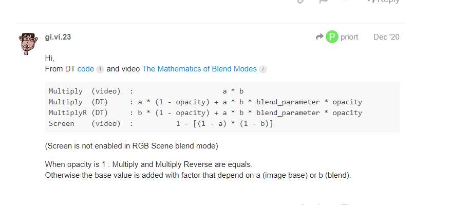
What I’ve readen is:
When you use a reverse blend mode the final image is mixed with the image with the module applied in “normal” mode.
If you use a known blend mode, for example “multiply”, the final image is blended with the input image of the module.
If the opacity is set to 100% “multiply” and “multiply reverse” gives the same results (without masks).
Use a landscape picture (for example) and in Local contrast, apply a multiply blending with opacity of 30%. And change from multiply to multiply reverse. You will see the difference
I have been wondering if the observed result is produced by this sort of arrangement
“Maybe its like the input / output saturation sliders in color balance, ie you can reduce a bit the input before calculation. So when you drop opacity and the blend order is reversed then the masking now on the input image, so you are blending the output in multiply to a reduced opacity input and so the effect is a less overwhelming darkening of everything and thus sharper and bringing out the darkest parts a bit more. .So at 100% opacity they would be similar or very much so but not at lower opacity…does that make sense maybe??”"
Experience is the best reminder…I have quite a few presets with low opacity multiply so I just use them….if I had experimented more with the new one I would have likely discovered the nuance of it. I love your edits by the way. I think that you and Boris are great ambassadors for the software. There is a lot of math and technical talk around DT but you and Boris put some creative and artistic flare into it……
The problem of “reverse” blend modes in scene referred is that they respond in a strange way to masks.
Unless I am missing something, there is no way to restrict the effect to a part of the image with a drawn or parametric mask, some effect is applied also outside the mask.
I’m “studying” the code where these blending modes are done “blendif_rgb_jzczhz.c” but I have some difficulties to understand everything.
I see that “blend fulcrum” slider is related with the “p” value in the functions (but I didn’t find where it’s created this “p”.
In “blend_subtract” and “blend_subtract_reverse” the “b” array goes till “j+3” and in others goes to “j+DT_BLEND…”
I’m not a software man as you can see. If I understand everything I will try to find where the problems are. Because I’ve detected they the mask is lost when I do some operations (I have to identify exactly when it happens)
This shows a case where, for example, we have a normal “Multiply” operation. See the slider at the top right, it takes a copy of the input image, and a copy of the output of the module+blending operator. The position of the slider for each pixel slider is then controlled by the value of the mask at that pixel position. If the opacity is set to 0, you get 100% the input image, and if the opacity is 1 you get 100% of the output from the module+blend operation.
In the case of multiply reverse, the top of the slider doesn’t connect to the input image, it cnnects to the output of the module, just before the blend operation. This means the final output of the slider is a mix between the module output (eg. local contrast enhancement, for the local contrast module) and the output of the blend operator (eg. multiplying the pixel from the input image with the pixel from the output of the contrast enhancement, in the case of a multiply blending operation). In this case, both sides of the slider input are coming from the output side of the module, which means that the effect of the module (eg. local contrast) will be present in some form regardless of where the mask sets the slider.
Probably we should provide a second copy of that diagram showing the logic of the “reverse” blending modes. The documentation is a bit vague on blending modes in general, passing the buck to the GIMP documentation. I think this was an attempt to keep the documentation from growing too much and being difficult to maintain as new blending modes are added, but it does make this aspect of the darktable behaviour more opaque.
I was not disputing the formula’s merely pointing out that with reverse multiply you get an effect outside the mask due to the layer that is blended but with the other 2 “reverse” modes don’t behave that way and so the author proposed that maybe they should be renamed as it was misleading somewhat…Maybe the situation has been updated…
„not recommended to use“ doesn’t imply that this module messes up everything. You need to know what you‘re doing - it can cause a messup for one image and be fine for another…
If something was messed no one can give help without having the image and xmp