Unfortunately I cannot calibrate my monitor. I might spring for a device to do it soon. So this leaves me with a few options. Default windows sRGB, Acer driver, OS software/windows tweaked Acer driver and some of Elle’s profiles. Using most of these I see some channel overflow moving the matched input output slider in each color channel and setting R-R or G-G or B-B to zero does not zero that channels pixel value. If i use DT sRGB or any of the linear DT profiles there seems to be no spill over and I can zero a pixel. The DT AdobeRGB is somewhere in between what I get from not-DT profiles and the well behaved DT profiles. Hopefully if I had a calibrated profile and things correctly set in the OS then I should be able to use that. Its not a huge issue as I would rarely try to use the Channel Mixer to set some exact rgb color and in general the changes you make with the sliders are predictable except at extremes. For my display the gamut is close enough to sRGB I can also use the DT sRGB profile is I want so its all good
Thanks for all the remarks, it went a bit off topic with the discussion about profiles but it is very interesting. My remark on presenting the matrix transformation with line vectors is only to say that the documentation got me very confused with the place of the coefficients in the UI.
Mathematically, using column vectors instead of line vectors has nothing to do with habit or convenience, it depends on whether you are in \mathbb{R}^3 or in (\mathbb{R}^3)^\star if my memory serves me well. I agree that column vectors are easier to present but the sliders do not correspond and probably for a good reason.
I ended up using a simple diagonal matrix.
I don’t know if I can get back to the idea behind my post or if I need to make a new one…
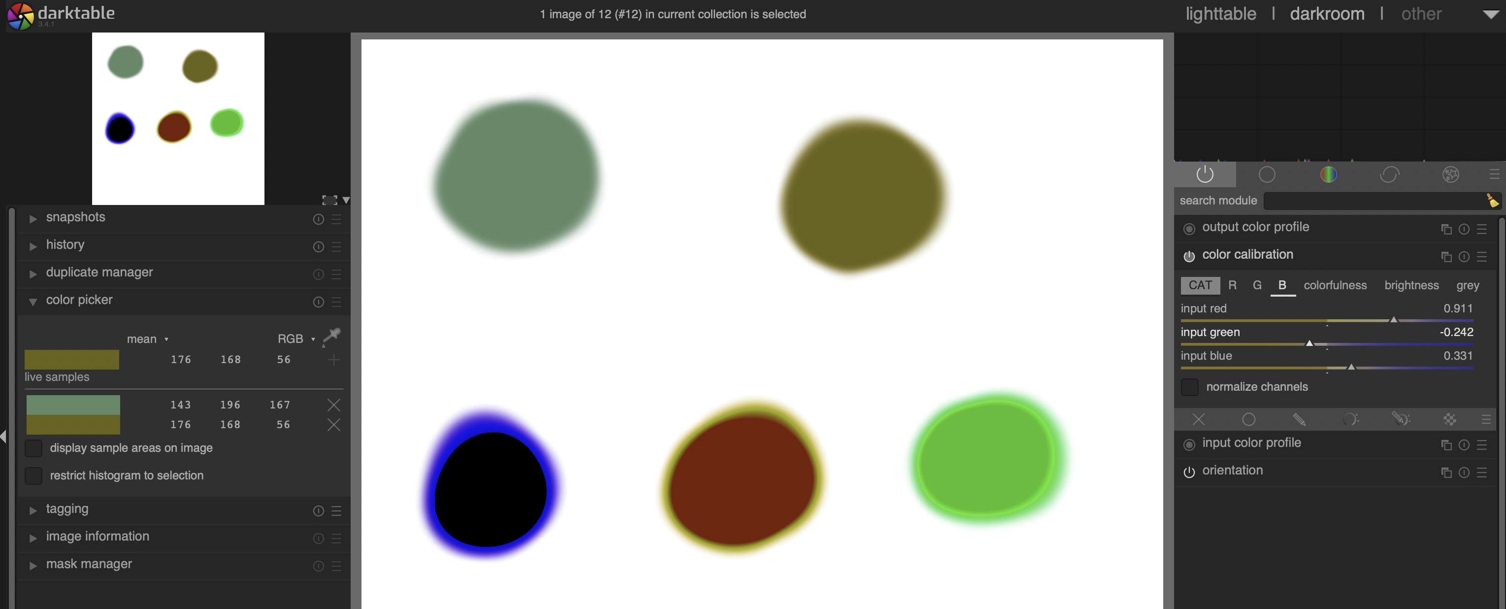
I would like to use the channel mixer to transform my purple patch to green while not having a hue shift (hence the sums equal to 1).
I tried in Xcas with
linsolve([69rr+203rg+129rb=152,69gr+203gg+129gb=155,69br+203bg+129bb=199,rr+gr+br=1,rg+gg+bg=1,rb+gb+bb=1],[rr,rg,rb,gr,gg,gb,br,bg,bb])
but got no solution.
I am sure there is another method to calculate the correct coefficients but I do not know them.
I don’t really know any maths software that could help either and I can’t be bothered to solve it by hand.
I think you’ll have to lay more constraints. At present the system has six equations but nine unknowns so there’s no exact solution.
You could come up with three more constraints (equations). Two options come in my mind right now: you could constrain the matrix to be symmetric, or you could constrain the off-diagonal elements on each row to be equal to each other. Not sure if either is photographically meaningful (or meaningful for your use case).
Edit: of course you could also specify another color that you would like to transform into some other color. That also generates three additional equations.
If M is the 9x9 matrix representing the equations then det(M)= 0 so I could have no solutions or an infinite amount of solutions. With 6 equations, potentially, I could have 3 parameters (the solutions are \simeq \mathbb{R}^3) so no problem there.
More constraints would reduce this space to a single solution in the best of cases (when det(M)\neq 0).
In this case, there seems to be no solutions.
A quick example :
In two dimensions, the equation x+y=1 has an infinite number of solutions. It is a one-dimensional space. If I use x as a parameter, then y=1-x and I get the equation of a line.
I see. My linear algebra is pretty rusty so I might be getting this wrong, but…
Essentially we are talking about pixels as vectors in \mathbb{R}^3 where the components are (R, G, B). You’d like to have (1, 1, 1) as an eigenvector of the desired linear mapping, with an eigenvalue of 1 to avoid changing the neutral tones.
Then you also desire to change the purple patch to green. One thing that immediately comes into my mind is a rotation around the (1, 1, 1) axis. That satisfies the desired eigenvector and eigenvalue and doesn’t change the neutral tones.
However rotations also have the property of preserving the Euclidean norm. Your purple patch has |(152, 155, 199)| \approx 294 while the green patch has |(69, 203, 129)| \approx 250. Hence it’s not possible to exactly map the colors to each other by just a rotation. One would have to additionally introduce a scaling but then the neutral colors would change in luminance.
If the patches had the same Euclidean norm, it would be possible to find out the rotation by the axis-angle representation – now the only free parameter is the rotation angle, and that can be found by projecting the green and purple vector into a plane that is orthogonal to the vector (1, 1, 1) and calculating the polar angle between the projected vectors (perhaps there’s also a simpler way that I can’t recall).
If you then would like to return the patches to their original scale, just add a scaling after (or before) the rotation. That’ll of course also scale the neutral colors.
I don’t know if it’s possible to find out a matrix that both preserves the neutral vectors and does the transformation between the green and purple patches you have given.
Thanks, this is very helpful. If I understand correctly
(1,1,1) is an eigenvector so I do not add a cast to greys.
1 is an eigenvalue so I do not lighten/darken greys.
I haven’t done this for a while but I will try out the calculations.
The plane that is orthogonal to (1,1,1) and that passes through (0,0,0) has the equation r+g+b=0
The projection of a colour (R,G,B) on this plane is easy. If S=R+G+B then the projected point has coordinates (R-\frac{S}{3}, G-\frac{S}{3}, B-\frac{S}{3})
Got to go to work now so I’ll carry on later.
I’ve come to the party a bit late, but - treating color as a vector space - much of this falls into the framework of choosing axes of rotation, then choosing what angle to rotate that axis to achieve a desired effect. The result of these choices are “pure” rotation matrices that do not scale or translate and transform your colors from the original to the (hopefully desired) new orientation. The links below point to G’MIC documentation, but the underlying theory is generally applicable.
- Orientation
- Norm
-
Mix RGB
This last page is somewhat analogous to paint program color mixers. The top illustrates a 190° rotation around the white vector which carries orange to cyan and green to purple. Note that the grey values are unchanged, the shadowed grey wall in back has colors are on (or near) the axis of rotation, so will not change/rotate at all (or a very little).
At the bottom of the page are two animations of the same image. Different colors were chosen in each to serve as axes of rotation and the animations reflect 360° revolutions around those axes. Note that on the left, a sky color was chosen as an axis of rotation, while beach sand was chosen on the right. Neither axial color changes much, while the color climate on the whole changes alot.
- Rodrigues Rotation Formula goes into the math on choosing axes, rotations, then finding the appropriate rotation matrix.
Hope this helps.
Here is the computational exercise. There are three tasks:
-
What scaling occurs between the purple vector (152,155,159) and the green vector (69,203,129)? Approach: Find the norm (length) of the two colors. We are going from purple to green so the scaling ratio is norm([69,203,129])/norm([152,155,159]).
-
What is the angle between these two vectors? Approach: find the dot product between their normalized lengths. That is the cosine of the angle separating them (i. e., the angle of rotation).
-
What is the axis of rotation to align the first vector with the second? Approach: find the cross product. That is a vector perpendicular to the plane formed by the first and second vectors. This is the “axle” upon which our color vector “spokes” turn.
I’m going to use G’MIC as a “desk calculator” to compute numerics for these approaches. I’m on Gentoo Linux, in a bash shell.
- Norm of green:
gmic echo '{norm([69,203,129])}'
[gmic]-0./ Start G'MIC interpreter.
[gmic]-0./ 250.22190151943136
[gmic]-0./ End G'MIC interpreter.
- Norm of purple:
gmic echo '{norm([152,155,159])}'
[gmic]-0./ Start G'MIC interpreter.
[gmic]-0./ 269.09106265351886
[gmic]-0./ End G'MIC interpreter.
- Scaling needed to bring the purple vector to the same length as green
gmic echo '{250.22190151943136/269.09106265351886}'
[gmic]-0./ Start G'MIC interpreter.
[gmic]-0./ 0.92987815742366964
[gmic]-0./ End G'MIC interpreter.
This scaling factor answers 1st goal. Going for the angle between them…
- Normalized purple:
gmic echo 'np={[152,155,159]/norm([152,155,159])}'
[gmic]-0./ Start G'MIC interpreter.
[gmic]-0./ np=0.56486454251256535,0.57601318479899755,0.59087804118090725
[gmic]-0./ End G'MIC interpreter.
- Normalized green:
gmic echo 'ng={[69,203,129]/norm([69,203,129])}'
[gmic]-0./ Start G'MIC interpreter.
[gmic]-0./ ng=0.27575523797480894,0.81127990302733644,0.51554240143116459
[gmic]-0./ End G'MIC interpreter.
- What is the angle between these two normalized vectors?
gmic echo '{180*acos(dot([0.56486454251256535,0.57601318479899755,0.59087804118090725],[0.27575523797480894,0.81127990302733644,0.51554240143116459]))/pi}'
[gmic]-0./ Start G'MIC interpreter.
[gmic]-0./ 21.921694158353283
[gmic]-0./ End G'MIC interpreter.
This angle answers the second goal. Going on…
- What is the axis of rotation?
gmic echo '{cross([0.56486454251256535,0.57601318479899755,0.59087804118090725],[0.27575523797480894,0.81127990302733644,0.51554240143116459])}'
[gmic]-0./ Start G'MIC interpreter.
[gmic]-0./ -0.18240825940294053,-0.12827390787031406,0.29942459842229963
[gmic]-0./ End G'MIC interpreter.
This is the third answer. Now:
- What is the rotation matrix from the purple normalized vector to the green normalized vector?
gmic echo '{rot([-0.18240825940294053,-0.12827390787031406,0.29942459842229963],21.921694158353283)}'
[gmic]-0./ Start G'MIC interpreter.
[gmic]-0./ 0.94495535705056655,-0.28728666513312368,-0.15660697691394462,0.31156251830631981,0.93623064757583974,0.16248375834632819,0.099940834337423984,-0.20233276199472081,0.9742039227264111
[gmic]-0./ End G'MIC interpreter.
- Test. Does it rotate my purple vector to green?
gmic echo '{[0.94495535705056655,-0.28728666513312368,-0.15660697691394462,0.31156251830631981,0.93623064757583974,0.16248375834632819,0.099940834337423984,-0.20233276199472081,0.9742039227264111]*[152,155,159]}'
[gmic]-0./ Start G'MIC interpreter.
[gmic]-0./ 74.203271846734737,218.30817073388195,138.72785242360609
[gmic]-0./ End G'MIC interpreter.
Doesn’t look quite right, but remember the rotation matrix doesn’t scale, yet from the first, we see that the norms of the two vectors are different, so we have to account for this scaling; recall this is the 1st goal: scaling factor 0.92987815742366964.
gmic echo '{0.92987815742366964*[74.203271846734737,218.30817073388195,138.72785242360609]}'
[gmic]-0./ Start G'MIC interpreter.
[gmic]-0./ 69.00000169964936,202.99999955255402,128.99999979500561
[gmic]-0./ End G'MIC interpreter.
That looks like the green vector we were targeting, allowing for a little computational fuzz factor.
Might be convenient to compose the scaling and rotation matrices into one transform:
gmic echo '{mul(diag(vector3(0.92987815742366964)),[0.94495535705056655,-0.28728666513312368,-0.15660697691394462,0.31156251830631981,0.93623064757583974,0.16248375834632819,0.099940834337423984,-0.20233276199472081,0.9742039227264111],3)}'
[gmic]-0./ Start G'MIC interpreter.
[gmic]-0./ 0.87869334626180662,-0.26714159482637984,-0.14562540713243,0.28971518044495903,0.87058042949139092,0.15109009782235647,0.09293279888506803,-0.18814481591009288,0.90589094861974617
[gmic]-0./ End G'MIC interpreter.
This is the rotation and scaling matrix to carry the purple color to green:
| 0.87869334626180662, -0.26714159482637984, -0.14562540713243    |
| 0.28971518044495903,  0.87058042949139092,  0.15109009782235647 |
| 0.09293279888506803, -0.18814481591009288,  0.90589094861974617 |
Test that it works:
gmic echo '{[0.87869334626180662,-0.26714159482637984,-0.14562540713243,0.28971518044495903,0.87058042949139092,0.15109009782235647,0.09293279888506803,-0.18814481591009288,0.90589094861974617]*[152,155,159]}'
[gmic]-0./ Start G'MIC interpreter.
[gmic]-0./ 69.000001699649374,202.99999955255404,128.99999979500558
[gmic]-0./ End G'MIC interpreter.
Got the target vector again. Stick the matrix into Darktable and see if it plays for you.
Not a matrix that one could readily intuit oneself to, but if you can see your way to the scaling from one vector to the next, dotting for the angle in between them and crossing for the axis of rotation they rotate on, then you’ve got a grasp of the mechanics and you can work out the transform between any two arbitrary colors. Have fun.
Thanks Grosgood for giving another approach. I think I understand the channel mixer now.
In the attempt to rotate around the line passing through (0,0,0) with directional vector (1,1,1) so not to shift neutral colours, I have got the rotation done.
I wrote a code in Python

colors.py (1017 Bytes)
I also made a quick figure in geogebra

So colour A is rotated correctly and my Python code gives the same color as the predicted point A’ in geogebra. This rotation does not take into account the distance between A and the neutral line so that A’ is not on the line that passes through B.
The matrix entered into DarkTable gives the predicted colour.
Now I think I would need to scale out from the neutral line to reach the line passing through B and I would get something close (brightness would still be wrong).
No - Not another approach. It’s a different, incompatible approach - one to solve your original problem. But you’ve moved on to a different problem, and that is OK! Just don’t conflate the two approaches as being one and the same, because they are not. In your different problem, you’ve added the constraint that grays and whites cannot change. In my terminology, that means you’ve constrained yourself to rotate only on the normalized white vector. Grays and whites are exactly on that axis and would not change under rotation. In this new problem, you are interested in finding the angle of rotation of the white vector axis that minimizes the angle between your rotated (originally purple) vector and the target green vector. In general, they won’t be colinear but there is a minimum angle that can be found as the purple vector is rotated by the white vector axis. The white vector, your chosen axis of rotation, is the normal of a plane that you project both the purple vector and green vector onto, and the angle between those two projections is, I believe, the rotation you seek to get the minimal solution. That is, you align the projection of the purple vector with the projection of the green. The rotated, unprojected purple vector will still form an angle with the stationary green vector. The two won’t align, but it will be a “best” solution that still preserves the grays. My approach finds a matrix that exactly aligns the the purple and the green, making them one and the same, but it harnesses a different axis of rotation, so it will not preserve grays. If preserving grays is important, discard my approach and go with yours. Have fun!
I understand they are both different methods to solve the initial problem. The easiest is just a diagonal matrix
Skews the colours badly though (and I’m not sure what it is geometrically… a kind of scaling ?)
Flannelhead suggested keeping the grays neutral, that is what I implemented. The angle, for me is unique, not a minimum. I do not reach the target without scaling in a perpendicular direction from the white line and also darkening parallel to the white line. I do not know if this can all be done with one matrix, I do not think so and it does not really matter.
Your suggestion is interesting too, the changes to the other colours are less radical.
The number of solutions is infinite.
It is all an exercise to understand a bit what is going on in the channel mixer.
I wonder though if it would be a good idea to have a tab with rotation slider, a chroma slider and a luminosity slider. It would me more intuitive to transform a colour into another. This kind of thing is used to modify the colour of an object in conjunction with a local mask.
I’m having fun though. Hadn’t done any linear algebra in years!
It’s possible to use some ycbcr color spaces, the rgb->yuv->rgb conversions are just matrices.
With a matrix is possible to do hue, chroma and luminance corrections too, from ycbcr the hue should be calculate using atan2 (like lab to lch conversion)
Then the hue correction is done directly in the cb, cr channels
https://docs.microsoft.com/en-us/windows-hardware/drivers/display/processing-in-the-8-bit-yuv-color-space
For example if we want to rotate the hue about 180 degree using bt.601 ycbcr color space the correction matrix is :


matrixyuv-hue.py (509 Bytes)
Great timing, I’ve been looking for something like this recently. Are these values also correct for linear rec 2020?
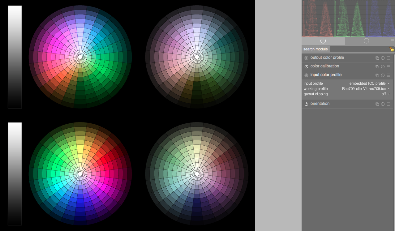
Edit: However, is this designed to be a normal hue 180 shift? Because aside from the flip, there is little hue variance, and yellow ends up in a strange place:

Compared with just entering 0,0.5,0.5 in each tab.

The above were done using linear rec 709 as working profile, as I don’t have 601. Here is one on rec 709, so its a solution that definitely seems intended for non-linear gamma (but still a problem with yellow):
Fun is good! Life is a tedium otherwise.
I believe it was Winston Churchill who observed that the English-speaking peoples are separated by a common tongue.
The approach you settled on, and demonstrated with python, addresses a different problem from the one you first proposed. New input statements. Even the initial steps are changed.
That want is the initial problem. Put another way, it seeks the transformation matrix that rotates and scales (152,155,159) so that it becomes (69,203,129). That is achieved by the “scale, dot, cross” process I presented this morning, arriving at a composite matrix that takes (152,155,159) to (69,203,129) - exactly! - around an axis of rotation that arises from the cross of those two vectors, normalized ( [-0.18240825940294053,-0.12827390787031406,0.29942459842229963], which doesn’t look anything like the white vector at all). Here is a demonstration of its effect:

Unaltered colors: Left top patch is to be rotated to match the right top patch

Altered colors: Left top matches right top exactly, but grays now have a green cast
By post 41, “not having a hue shift” was your first step toward casting vectors around the white axis, so that grays of all luminosity remain unchanged. You are - in a perfectly fine way - sharpening the idea of what you want to do. But this new problem is largely unrelated to the old, the commonality just being the goal of making the purple color as much like the green color as possible (best approximation), while constraining rotations around just the white vector - no other axis allowed! That’s a different matrix that has to satisfy different input requirements.
And your python script solves that problem! It finds the projections and determines the angle that the purple projection has to rotate to align with the green projection - about a 90.1838 degree rotation around the white axis. But when the unprojected purple vector undergoes this rotation, the resulting vector from that does not exactly align with the green target: something like 15.0351 degrees separate the two after the 90.1838 degree rotation takes place. Recall that we align just the projected vector images, not the unprojected originals. That 15 degree gap is the give-up we accept to keep all of the grays unchanged, because they are a part of the white axis around which we are constrained to do all rotations.
A 90.1838 rotation around the white axis gives rise to a new rotation vector that produces these changes:

Before

After
Not an exact color match, but grays are unchanged. That 15 degrees is a minimum angular separation. Rotate some more, and the gap grows - ditto if you rotate back. So long as we’re constrained to rotation around the white axis - only - ! then 15 degrees is the smallest angular separation you have to suffer with. It is the angle of separation between the plane the purple vector is rotating within and the green target vector. The moment you start thinking along the lines of pinning those two vectors together, scale and rotate them so they match, then you are back to your original problem statement - and the solution outlined for that will give you an exact match, but that will be obtained by introducing a rotation around another axis entirely, and most likely the grays will acquire a hue. So, you can have one, or the other - but not both. c’est la vie. I think the path you eventually followed is, aesthetically the best. Shift the colors, keep the monotones.
Thanks for the problem!
Thank you for taking the time! I now understand what you said about the angles, I was thinking in the projected spaces.
What do you think about the sliders I proposed ?
To broaden the discussion, who says hue rotation has to be the same for all colours? Perhaps it could be adjusted based on colourfulness, HVS, spatial location and so on.
And in practical work, it is only at the outset that some global adjustment is made to obtain an overall, approximate result. Soon begins any number of cycles of selecting specific pixels and applying local adjustments using a variety of tools. Matrices are involved in each case, but the tool’s UI usually hides those details. Over time, nearly every pixel has had a unique sequence of matrices applied to it, not quite the same as those applied to immediate neighbors. Only in rare cases does a tool expose matrices directly, like G’MIC;s ‘-mix_rgb’, and it is almost impossible to suggest how to use such tools intuitively. Such direct-matrix approaches are never easy to use. That’s why UI designers develop more intuitive abstractions that compute matrices automatically, hiding the details from users.
This is an example of designing a ‘wrapper’ that allows a more intuitive approach than the matrix-oriented channel mixer. I’m sure it could be easier. But UI’s will always have a raw, direct way to get at matrices. One can do anything with matrices, so long as one can get past their non-intuitive nature.
Exactly. Matrices populated with non-zero coefficients only along the diagonal just scale each axis of the space. In your specific example, the matrix scales the R component of every hue by 0.45395, G by 1.30968 and B by 0.64824. What was a cube in color space transforms to a rectangular parallelepiped by this matrix, lengthened in green but contracted in red and blue. This kind of matrix is analogous to a tool with uncoupled R G B scaling sliders, each which scale only along one color axis.
Probably with rec.2020 would be only slightly better to use the appropriate matrix .
A generic yuv conversion could be the one where the luminance is calculated as the rgb average Y=r * 1/3 + g * 1/3 + b * 1/3, like darktable’s y0u0v0 .
However the matrix most simple and easy to invert is with Y= r * 0.3 + g * 0.4 + b * 0.3, very close to y0u0v0
rgbtoyuv=[ [ 0.300 0.400 0.300 ] [ 0.500 0.000 -0.500 ] [ 0.250 -0.500 0.250 ] ]
yuvtorgb=[ [ 1.00 1.00 0.800 ] [ 1.00 0.000 -1.200 ] [ 1.00 -1.00 0.800 ] ]