Create lens calibration data for lensfun

Not really. The mechanism I described is by far the best one to determine if the DNG converter knows about the coefficients or not.

A weaker methodology would be to try taking pictures at a fixed focal length with different focus distances on a lens which exhibits focus breaking. Good in camera corrections will account for this and so the set of coefficients exiftool shows will change as a function of focus distance (assuming a fixed aperture and focal length). If this is the case (and it is easy enough to test) then you can try running those files through the converter and inspecting the coefficients. If they do not change then you can be reasonably sure that the converter is not using the embedded coefficients. (This works because hand-tabulated coefficient tables often fail to account for focus breathing. Lensfun is an example of a system which exhibits this flaw—yet another reason why I do not recommend it.)

Of course, if the coefficients do change then we’ve not learned a lot. They may change because the NEF coefficients have changed or because the converters own tables account for focus breathing.

Regards, Freddie.

1 Like

Does someone know if the script calculating vignetting correction data uses the smallest aperture as reference image that has no vignetting?

As it’s almost impossible to take a photo of a constant background, that’s what I assume, but if it’s not the case, then it needs a very good studio environment to achieve this. I tried the method with a “uniform” sky, but there is no such thing, and the result was in fact quite asymmetric.

If all the photographs are taken at the same place and in a short time span, I suppose that it’s possible to compare the different apertures to get an idea of where the vignetting is centred, and from there, how much it increases with the aperture and focus distance (by default of an absolute reference).

There’s also the annoying fact that, at the smallest aperture, every single dust particle is visible on the image at inf.

After worrying with uneven skies etc I bought myself a flatfield mask to optimize vignetting correction Flatfield Masks < Masks < Astrophotography | ASTROSHOP

1 Like

This is why you use a piece of white acrylic on top of your lens.

@paperdigits No, I’m using the same one as in the first post and that’s not enough. It’s a very misleading idea.

The acrylic will slightly diffuse the light across neighbour pixels, but not across the whole picture.

When you take a photo of the sky, even when there’s a “uniform” layer of clouds (diffusing the light as the acrylic does), the sun is still the unique source of light. When I tried, there was a strong bias of light in the direction the sun should have been, as expected, even though the sky was entirely covered with a constant stratus / nimbostratus layer and looked uniform - don’t forget our vision is mostly impacted by local differences, as this famous image illustrates.

I get a much more symmetric result using it against a screen, but the light is still varying a little with the angle.

That’s a nice solution but a very expensive one. :slight_smile:

1 Like

OK well then get some of this: Amazon.com: Falken Design Acrylic Plexiglass Sheet, White Translucent 32% (7328), 12" x 18" x 1/4" : Industrial & Scientific

I’ve done this for numerous lenses using this and the exact method described here.

You can use this instead of Adobe DNG Converter. It reads Nikon lens correction data Iridient Digital - Iridient N-Transformer

"Automatic lens corrections for distortion, chromatic aberration and vignetting. Corrections are based on native Nikon lens information specified in their NEF metadata. The lens correction stage is optional and lens correction information can also be passed on through DNG opcode metadata and left to later processing stages or ignored altogether. The lens correction processing in Iridient N-Transformer uses the same high quality resampling algorithms as Iridient Developer."

The version for Canon does the same thing.

Interesting. Thanks for sharing @Peter!

1 Like

The answer to my own question is: those scripts apparently don’t. They take all the samples and try to fit a curve. If the discrepancy isn’t too big, it’s still possible the curve will be more or less correct, but it could benefit from some improvement.

@system Another note to add to the first post: The VM is so old that it doesn’t recognize the NEF files, so they’ll have to be converted to DNG with Adobe’s DNG Converter first.

No, that’s the same problem I described before. Using another plate won’t make the sun omnipresent.

The idea of using those acrylic plates is flawed anyway because the light attenuation depends on the angle of the rays coming into the lens (thicker material when the angle is not 90°), exaggerating the vignetting perceived by the scripts.

Forget the acrylic plates. You need something like @piratenpanda posted or a studio setup with a surface that is evenly illuminated and gives a uniform reflection from any angle the lens can see.

PS: Now I understand why some lenses’ vignetting was over-corrected in Darktable. :frowning:

I just recently took pictures for flat field correction in RT using a sample sheet (3x100x75 mm) of PLEXIGLAS(R) LED WH72GT. Pictures were taken with a cloudy sky where the sun could still be seen through the clouds. I took the pictures on a hill with no surrounding objects with the camera overhead , the lens pointing up into the sky and the sheet lying flat on the lens. The pictures showed symmetrical vignetting, but different color casts towards the edges. Two pictures taken with the same settings but the camera turned 180° (to have the sun to the opposite side) showed identical vignetting and color casts.

Therefore, acrylic plates can be used with good result when the following conditions are met:

  • The acrylic sheet is white with low transmission, i.e. maximum scattering within the sheet.
  • The top surface of the sheet is illuminated only from a distant cloud cover, giving even illumination strength across the sheet.
  • The direction to the sun is outside of the field of view of the lens (this avoids direct transmission of sunlight through the sheet onto the sensor).
  • the edges of the sheet are evenly lit (as an alternative, you may also paint the edges evenly black). Do not hold the sheet with your fingers.

I got my sheet as a product sample from the manufacturer. It seems not to be available at the moment, only the WH52GT sheets with higher transmission are currently available at PLEXIGLASÂź LED White WH52 GT

What’s “RT”?

Those conditions were met when I took the samples (except the “evenly lit”, which is impossible IMO). Maybe it’s less noticeable with long focal lengths, though, but I don’t know what you measured.

For a 35 mm, I would strongly advise against it. You’d get 15% less illumination in the corners due to the thicker translucent material under those angles. That problem is independent of the uniformity of the scene and - worse - cannot be separated from the actual vignetting.

I’m getting better results taking shots at a surface like a painted wall and ambient day light, without any plate, and making a little of post processing:

  • duplicate the image, flip it horizontally, and average both
  • take the result, duplicate, flip vertically, average

This lessens the potential slope with a unique source of light (like the sun, ambient light from a window, etc), though it’s not perfect, and one must take care not to cast a shadow while taking the shots. I could see in the resulting curves that the discrepancy was much lower. I think this processing could be done in software; the current script in lens_calibrate.py computes a sort of average, but from the output, it’s obviously wrong).

Another possibility is to use Adobe’s Lens Profile Creator and convert the .lcp file with Lensfun’s conversion tool (must be compiled from the GitHub repository). Adobe has an interesting procedure involving multiple shots of a checkerboard image. It’s more involved but seems less lax. On the down side, the software’s a black box.

1 Like

RawTherapee.

I took my pictures with a Sony RX100 Mark 1 which has a 1’’ sensor and a Zeiss Vario-Sonnar 10.4 - 37.1 mm lens, equivalent to 28 - 100 mm full frame. The lens is very compact, retracting to less than 3 cm thickness, so the designers had to make heavy compromises on geometric distortion and vignetting to get a 1.8 - 4.9 aperture range. Here is a picture taken at 10.4 mm focal length and f 1.8 where vignetting is worst (this and all following pictures were processed in RT without applying any tone curve):

The estimate of 15% less illumination in the corners due to the thicker material at 35 mm focal length equivalent applies for a transparent sheet with a light absorbing dye, such as a neutral filter, but not to the translucent sheets which contain light scattering particles. The scattering within the sheet is amazingly homogeneous, as can be seen by the following pictures taken at night with the lens pointing upwards and the sheet being illuminated by a LED street lamp to the left, outside of the field of view, which without the sheet would have been only dark night sky.

I took a second picture with the camera rotated by 180°, so the street lamp was to the right. As you can see, there is no apparent difference, although the sheet is illuminated from the other side.

Correcting vignetting from a picture of an object requires a flat surface of even colour which scatters light evenly (i.e. it is matte and not glossy or reflecting) as well as even lighting of the surface.

With direct sunlight or another point light source at a sufficiently large distance, you will get even lighting. However, since you have to take the picture from the side to cast no shadow, you are prone to get brightness differences from non-uniform scattering. Here is an example of a flat gray polyethylene surface (the bottom of a collapsible crate) I photographed at 10.4 mm and f 2.8. In addition to the vignetting from the lens, you see the brightness falling from the top left to the bottom right hand side (the sun was in the back upwards to the left).

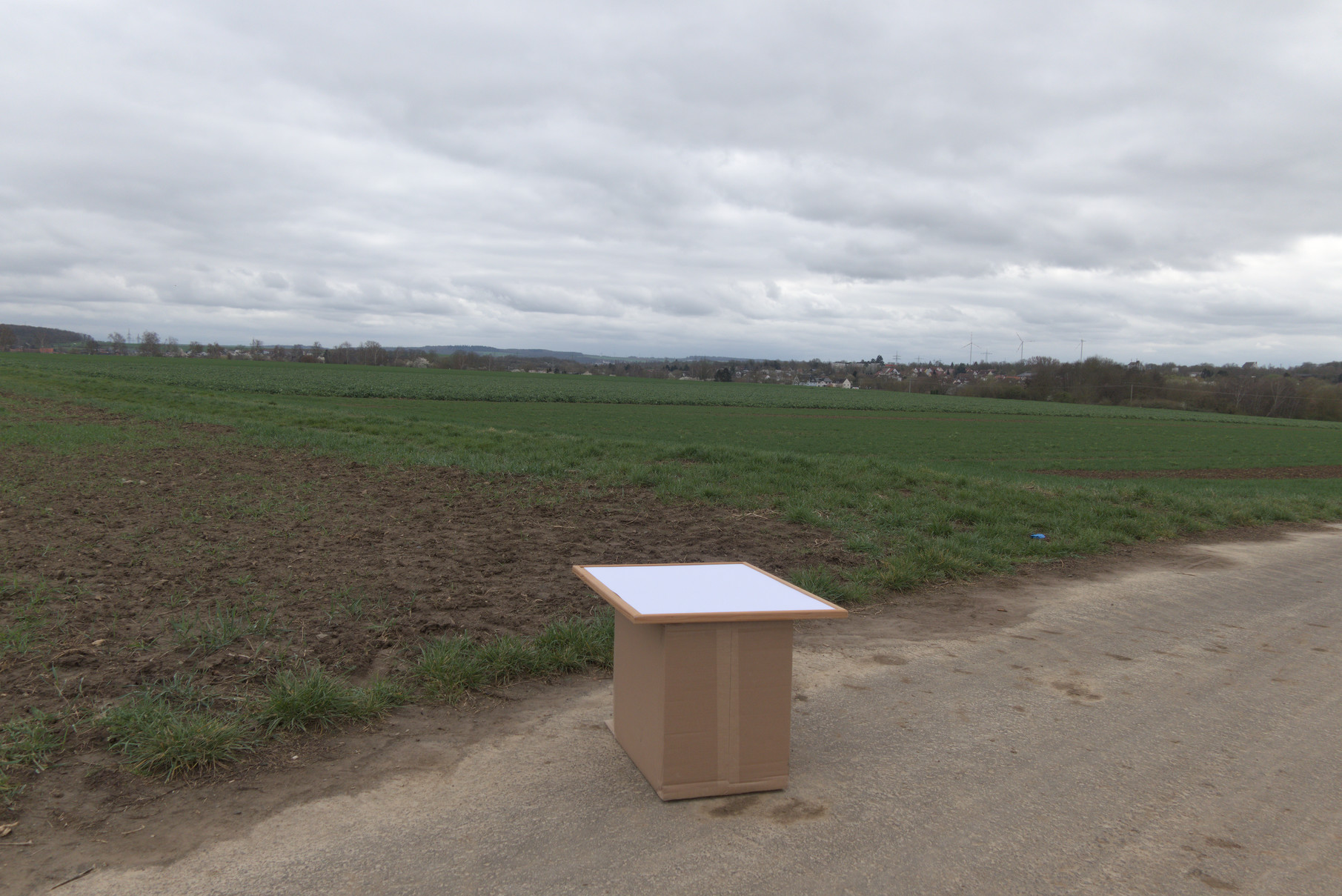
With a closed cloud cover, you can in principle get more even lighting from all directions to avoid problems with non-uniform scattering. I tried this with the following setup of a flat white cardboard sheet on top of a hill to get illumination only by distant clouds. The view is towards the position of the sun behind the clouds:

I wore off white pants and a white lab coat to prevent casting of shadows, stood at the side to the right in the picture and held the camera over the sheet pointing straight down for the first picture.
For the second picture, I rotated the cardboard sheet by 180°.
For the third picture, I rotated the camera by 180°, with the camera bottom pointing away from me (for all other pictures, the camera bottom was pointing towards me).
For the fourth picture, I walked around the setup to take the photo from the opposite side.
All pictures were taken at 10.4 mm, f 2.2 and focus distance at infinity.
Here are the pictures in order:


Upon close inspection you will see that the brightness distribution is the same in the first, second and fourth pictures with identical vignetting and colour casts in the corners and the same brightness fall-off from top to bottom, whereas in the third picture, the brightness fall-off is in the opposite direction from bottom to top. The brightness fall-off is apparently due to me blocking off light coming from the side where I was standing, wheres the direction to the sun had no observable influence.

Now here is the second picture taken of the cardboard flat field corrected with a picture taken through the acrylic sheet into a cloud covered sky at the same focal length and aperture:

At close inspection, you can see that, apart from the brightness fall-off from top to bottom, there is some over-correction of the vignetting, which confirms the observation that pictures taken through the acrylic sheet show darkening towards the corners in addition to the vignetting by the lens.

Since I observe the same additional darkening for the pictures taken through the acrylic sheet evenly illuminated only by a light source outside the field of view, this cannot be caused by different light path lengths within the sheet.

I have a working hypothesis for a possible cause and ordered more acrylic sheets to check it. I will post again when I can confirm it by experiment.

5 Likes

For information, I used lens_calibrate.py on images that I could finally take from an evenly lit surface, but the results were over-correcting.

The curves were very nicely fitting in the PDF, but when I applied the correction to the very images used for the calibration, they all presented a slightly U-shaped waveform in Darktable, and for some of them, it was quite visible (corners lighter than the centre). I don’t think that should happen.

I used exactly the same photos with calibrate.py, latest revision of the lensfun project, and it gave good results (I thoroughly checked on the same images used for the calibration and other photographs, for several distances and apertures).

Installing calibrate.py was rather easy on Linux (I use Manjaro), but using it required some peeking into the code because it’s poorly explained.

So my conclusion regarding this article:

  • DO NOT use an acrylic plate, since it exaggerates the vignetting. Find a studio-like setup or use one of those expensive calibration lights for astronomy.
  • Avoid lens_calibrate.py and use the lensfun calibrate.py instead. At least for the vignetting.
  • For the distortion, I got much better results with calibrate_lens_gui, part of the hugin tools.

PS: About this acrylic plate: assume it has a thickness d. The shortest distance of the rays inside the light-attenuating matter is d/cos(α), where α is the angle between the ray and the perpendicular to the plate (of course, there’s some distribution around that angle because it’s not perfectly transparent). With a 35 mm in full format, that’s about 17% longer than when perpendicular, so in the corners vs the centre of the photograph. Typical acrylic plates like the one mentioned in the article has a 70% transmission factor (hence 60% in the corners in my case). You’ll notice the attenuation is in 1/cos(α), so good luck to separate that from the actual vignetting, unless you add it to the script. There’s also a possibility to get more attenuation in the corners if some of the rays are reflected rather than diffracted at the interfact, which is not improbable. I could be wrong, but that’s also what I observed when I tried.

4 Likes

Interesting test results!

I need to do more tests, but if the sun is on one side or if a lamp is on the other side of the plate, I can see a difference (it’s more obvious when flipping the image or checking the waveforms). The plate has a 70% transmission, and it’s not that thick, just a few mm. I suppose a thicker plate should spread those rays even more, but shouldn’t the distribution remain centred on the source?

It’s a little the same as what you observe in the sky: the scattering does indeed a great job at spreading the rays coming from the sun in every direction, even when looking away from it, but the straight line is always favoured statistically.

However, the calibration algorithm does an average, so a slope may not significantly impact the results as I first thought. I’ll try to do some tests with a calibrated lens and with/without a plate, to see if I can spot some extra vignetting too. For longer focal length, it’s probably not a big difference.

I was also concerned by that; some amount of specular reflection rather than a good diffuse reflection could bias the result.

I took an evenly lit wall from an angle; the paint doesn’t show any noticeable specular reflection and it wasn’t a direct light. I can see a slight slope, but the algorithm averages the results to bin the results by angle. I first tried by averaging myself top/bottom then left/right, but the difference was not worth the trouble.

Before correction (flip horizontally to see the slope):


After correction:

1 Like

I would like to help create a lens profile for the Sigma 16-300mm zoom lens released a few months back. I have an M1 MacBook Pro. I am willing to do it but only if provided clear instruction on how to install the required modules on the Mac specifically. Do those exist ? Else I could take the RAW pictures and upload them for somebody else to run the calibration tools. No interesting in setting a LINUX system, never will. Let me know what is out there for Mac support, I could not find anything. Cheers.

Hi @Martin_Chalifoux welcome! All these packages are available on the Mac using something like homebrew or nix.

Thanks a lot for the tip. I used brew to install the modules. I installed dumpy but get the following error, maybe you can help.

martin@MBP16-MC Sigma 16-300mm % python3 -m venv .venv                       
martin@MBP16-MC Sigma 16-300mm % source .venv/bin/activate                   
(.venv) martin@MBP16-MC Sigma 16-300mm % ./lens_calibrate.py init 
Traceback (most recent call last):
  File "/Users/martin/Pictures/Lensfun calibrations/Sigma 16-300mm/./lens_calibrate.py", line 43, in <module>
    import numpy as np
ModuleNotFoundError: No module named 'numpy'
(.venv) martin@MBP16-MC Sigma 16-300mm % brew search numpy
==> Formulae
numpy ✔                                                                                     numcpp

==> Casks
numi
(.venv) martin@MBP16-MC Sigma 16-300mm %
1 Like