Diagonal interpolation correction artifacts with AMaZE Demosaicing

Hi @LuisSanz,
so today I was sick at home so I had some time to play with thisā€¦ hereā€™s what I found.
I think the differences are not due to WB, but rather to the way dcraw and RT deal with clipped highlights. Here is a patch to your dcraw.c that enables a further highlight mode -H 10, which tries to emulate what RT does (when highlight reconstruction is turned off):

diff --git a/dcraw.c b/dcraw.c
index ca28559..f30793b 100644
--- a/dcraw.c
+++ b/dcraw.c
@@ -10206,6 +10206,29 @@ next:
       else
 	ahd_interpolate();
     }
+
+    if (!is_foveon && highlight == 10) {
+        float dmin, dmax, q;
+        unsigned i, c, size;
+        int val;
+        
+        for (dmin=DBL_MAX, dmax=c=0; c < 4; c++) {
+            if (dmin > pre_mul[c])
+                dmin = pre_mul[c];
+            if (dmax < pre_mul[c])
+                dmax = pre_mul[c];
+        }
+        q = dmax / dmin;
+
+        size = iheight*iwidth;
+        for (i=0; i < size*4; i++) {
+            if (!(val = ((ushort *)image)[i])) continue;
+            val = ((float)val) * q;
+            ((ushort *)image)[i] = CLIP(val);
+        }
+        highlight = 0;
+    }
+    
     if (mix_green)
       for (colors=3, i=0; i < height*width; i++)
 	image[i][1] = (image[i][1] + image[i][3]) >> 1;

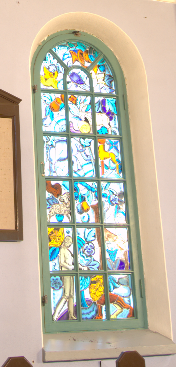
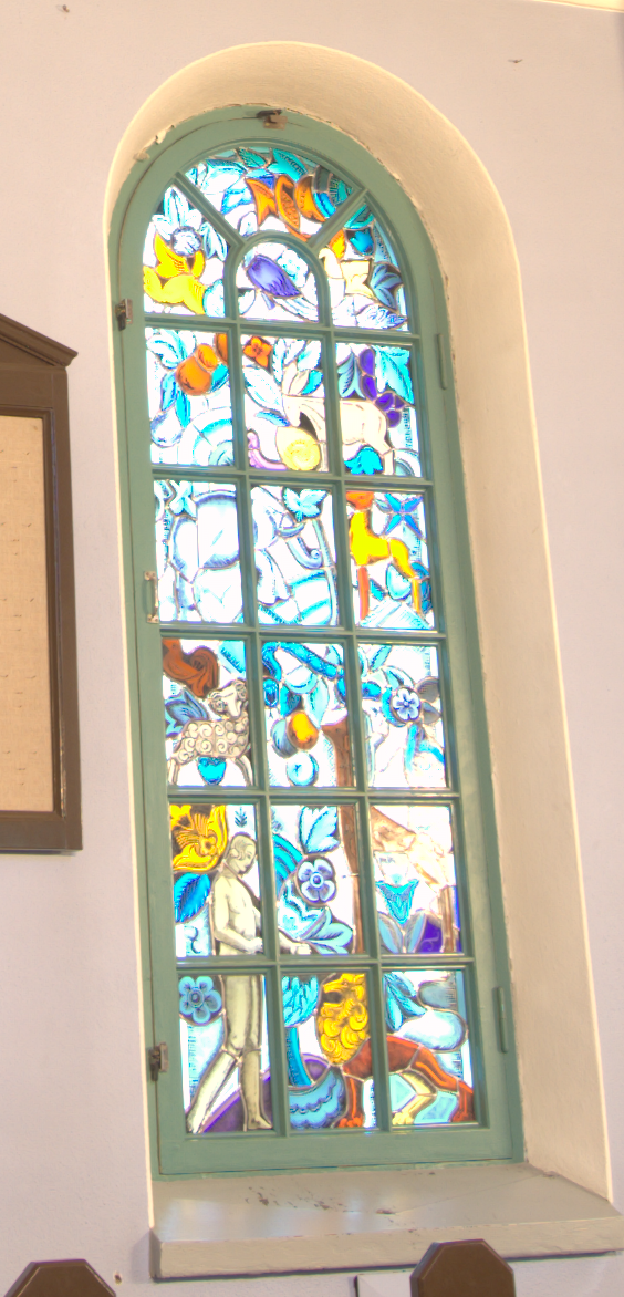
Here are three crops of your test image above, developed respectively with:

  • dcraw -v -T -4 -H 0 -W -o 1 -a -q 4 -c DSC_0934.NEF

crop-dcraw-h0

  • dcraw -v -T -4 -H 10 -W -o 1 -a -q 4 -c DSC_0934.NEF

crop-dcraw-h10

  • rawtherapee-cli -Y -tz -s -c ~/Downloads/DSC_0934.NEF
    (neutral profile, RCD demosaicing)

crop-rt

It seems to me that the dcraw image with -H 10 is very close to the RT one. What do you think? The difference between -H 0 and -H 10 is in the scaling of the raw values to normalize them to the range [0, 65535]. -H 0 is more aggressive in clipping before demosaicing, whereas -H 10 is more conservative before demosaicing, but then rescales the values later. This is closer to what RT does. As to why this has an impact on your algorithm, well, I have no idea :slight_smile: but I hope this could be helpfulā€¦

2 Likes

Bingo, @agriggio! I was also sure it was related to the highlight scaling rather than to white balance.

Is RawTherapee applying that normalization before or after demosaicing? In your patch to dcraw, it seems to affect negatively not only RCD but also PPG and AHD.

It reminds me to the same kind of effect that occurs when the white balance is applied after demosaicing.

Thank you very much for your findings and I hope you get well soon.

1 Like

after

WB is also applied after demosaicing in RT. it wouldnā€™t be trivial to change this Iā€™m afraidā€¦
do you think thereā€™s a way to compensate for this in RCD?

note that something similar happens also in the original dcraw when you use a nonzero value for -H

1 Like

Hmm, Iā€™m turning in my pixel peeping credentials. It wasnā€™t the lens, it was the bright sunlight. The artifacts from using UniWB for interpolating the raw file are much less noticeable for images shot under incandescent light. I wonder how obvious these artifacts might be for images shot under complete overcast skies.

At 400% and 800% zoom the artifacts become easy to see, even for images shot under incandescent light, once there is something to compare to. But - as Iā€™m sure everyone else already knew :slight_smile: - there really are artifacts from using UniWB as the whtie balance for interpolating the raw file: noisier shadows (color noise) and the wrong color and brightness for highlight pixels and along edges. In the future Iā€™ll use the correct white balance for the raw files even if it means outputting multiple versions for mixed lighting.

1 Like

folks, I think I read some time back, probably on Pixls, that itā€™s better to do the white balancing along with the demosaicing, rather than afterwards. If you want the best quality then, perhaps one should use DCRAW and input the factors. But how do you know what they are? Can you use RT to set the white balance wysiwyg, and somehow obtain the factors represented by the temp. and tint? I canā€™t see an obvious place where this is. Looking at the exif in a jpeg produced by RT, there is ā€œColourBalanceā€ at ā€œ10, 798, 1024, 1024ā€¦ā€ and MeasuredColour at ā€œ12, 442, 1024, 1024ā€¦ā€ but these donā€™t mean much to me and when I expand the pane, the "ā€¦"s remain.

@Elle, Iā€™m confused when you say

Why would you do this, wouldnā€™t you produce a green image? - but I might be confused!
Surely one would use the appropriate factors for the interpolating/demosaicing, not (1,1,1,1) ?

@RawConvert if you are interested, the RT issue mentioned above is worth reading. TL;DR: the current method in RT should work just fine in most cases, with the added benefit of not requiring any change :slight_smile:

I should also add that just enabling 1 step of false colour suppression gets rid of most of the artifacts you see above for RCD in RT

I see. I also think itā€™s more efficient for a software with GUI to apply the white balance after the demosaicing. Otherwise every change in temperature or tint would need a full reinterpolation of the raw data or to set up a rather complex system that is probably not worth the effort.

Any non-balanced scaling of the RGB channels after the interpolation would result in that kind of color misalignement near edges, since the demosaicing cannot take the decompensation into account in order to smooth it. Iā€™ll check if I can mitigate the issue in RCD.

1 Like

There are two very different issues here:

On the one hand, people will say ā€œYou canā€™t white balance an image after itā€™s been interpolated.ā€ This is not true. Whether you interpolate using UniWB or else use the actual white balance that you want the final image to have, as long as the image is still in the camera input profile you can change the white balance after itā€™s been interpolated, the colors will look just fine. Occasionally I have found it convenient to white balance an image after itā€™s been interpolated instead of before, for example when the lighting was mixed and I wanted to apply two different white balances.

On the other hand, not white balancing before interpolating can produce artifacts, which I didnā€™t realize was the case. The artifacts arenā€™t always obvious. My studio lighting, such as it is, is tungsten lighting, and when using tungsten white balance the artifacts from not white balancing before interpolated are not very noticeable. But if the desired white balance is daylight white balance, the artifacts are considerably more noticeable.

So at 400% zoom for tungsten white balance, I ddinā€™t notice anything amiss until I had the ā€œwhite balanced before interpolationā€ image to compare to the ā€œwhite balanced after interpolationā€ image. But at 400% zoom for daylight white balance, the artifacts are glaringly obvious.

Iā€™m guessing itā€™s the high red multiplier required for daylight white balancing that is key? But this is just a guess. Maybe there is a pre-interpolation white balance that is ideal regardless of the desired output white balance? What about images shot under completely overcast skies vs. images shot under daylight/sunlight? As I donā€™t know what causes the artifacts Iā€™m not able to generalize.

Good findings @agriggio and @LuisSanz. I had a suspicion that it had to do with wb and highlight mode. That is why I choose to compare output using that particular PlayRaw sample with its narrow spectrum, color imbalance, clipping and noisiness. I just didnā€™t understand what my own intuition was telling me or how to express it into words :blush:.

You canā€™t use RT to set the white balance and then somehow squeeze out the RGBG multipliers. Most raw processors provide several ways to set the image white balance, including setting the RGB multipliers. RT does not. I donā€™t know why, but maybe this is tied up with how RT pre-white-balances or something.

Across the various raw processors, the ā€œmeaningā€ of RGB multipliers is more or less constant, meaning setting the same RGB multipliers in darktable, ufraw, dcraw, photoflow, photivo produces pretty much the same final image colors. But as RT doesnā€™t provide access, you canā€™t share the same multipliers when comparing output from RT and other raw processors. The best you can do is hope that the presets and ā€œcameraā€ are the same for the raw processors you want to compare.

Unfortunately, the temperature/tint slider values for the various raw processors donā€™t correlate at all. The ā€œsameā€ temp/tint taken from one raw processor and fed to another will produce more or less different colors.

This page has summary information for various raw processorsā€™s options for setting white balance. PhotoFlow wasnā€™t released yet when I put together the information: Raw Processor Review, Part 1

When using dcraw, I find it convenient to get the white balance multipliers from UFRaw and then copy them over to dcraw using the ā€œ-rā€ multipliers. Open UFRaw, set the white balance you want, then click on ā€œOptionsā€ and select the Configuration tab - the white balance multipliers are available under ā€œā€.

The exif data in the jpeg comes from the raw file, and shows the white balance for various shooting conditions such as daylight, cloudy, etc, as given by the camera manufacturer. Use exiftool at the command line to examine the full contents of the raw file and the corresponding jpeg: ā€œexiftool filename.extā€

Hi @LuisSanz

I hope you donā€™t mind if I went ahead and tried to do this my own way :wink:
I just pushed my ā€œhackā€ to the rcd-demosaic branch in RT. It basically tries to compensate for the difference in highlight scaling between dcraw and RT. I would greatly appreciate your opinion on this :slight_smile: (Also, please keep in mind that I only took some undergraduate courses on image processing a long time ago, and Iā€™ve never worked with image manipulations sinceā€¦ so what Iā€™m doing is dictated purely by ā€œgut feelingsā€, and as such might be totally off!).

Anyway, for the curious, here are the results I get on the couple of test raws you posted above:

  • RCD in dcraw:

  • Original RCD in RT:

  • Tweaked RCD in RT:

  • RCD in dcraw:

DSC_0934-rcd-dcraw

  • Original RCD in RT:

DSC_0934-rcd-RT-orig

  • Tweaked RCD in RT:

DSC_0934-rcd-RT-tweaked

Best,
Alberto

2 Likes

I have just finished introducing the RCD demosaicing into photoflow. The implementation is based on the RT version, adapted to process small tiles in parallel.

Moreover, and following what @agriggio has reported, I have modified the RAW data clipping behaviour in photoflow, which results in much lower purple fringing around dark objects on clipped backgrounds. The improvement is actually visible for all demosaicing methods.

A small technical detail: I had to modify the code here and here to avoid inf values when the coefficients at the denominator are either equal but opposite, or very small.

Here is a comparison between Amaze and RCD with the new RAW clipping method:

Amaze:
DSC_0934-amaze-clip

RCD:
DSC_0934-rcd-clip

More details can be found in this other post on pixls.us.

For those interested, the photoflow code can be found here.

1 Like

So, inspired by what @Carmelo_DrRaw did for PhotoFlow, I generalized my ā€œhackā€ above so that it works with any demosaicing method, and not just RCD. Iā€™ve just created a new RT branch called highlight-smoothing (for a lack of a better nameā€¦suggestions welcome btw) that tries to get rid of the bad purple artifacts described above.
Thereā€™s a new option in the RAW tab, under ā€œPreprocessingā€, called ā€“ guess what? :slight_smile: ā€“ ā€œHighlight Smoothingā€.

Here are a couple of screenshots to show what it does:

  • AMAZE demosaicing, highlight smoothing turned off (the default, corresponding to the current behaviour of RT)

  • AMAZE demosaicing, highlight smoothing turned on

Now, if you are interested in this, you are very welcome to try it out, but please be aware that this is very experimental. It might actually be a regression for some images, I donā€™t know yet. I would especially like to hear about artifacts that are introduced by this trick, and under which conditions. In particular, one area that needs special attention is the interaction with highlight compression and the various highlight reconstruction methods.

2 Likes

Will you apply this for x-trans interpolation as well?

Yes, this is completely unaware of the CFA pattern ā€“ it does the same for all sensor types. I have tested only with Bayer cameras though, so feedback for other sensor types is welcome!

BTW, I should also add that you need to apply this on shots with significant portions of the pixels clipped, otherwise you wonā€™t see any difference.

Cool Alberto. I have some images from Venezia shot facing the sun, with strong clipped reflections on water. It will probably help in such cases.

Latest compiled test version ( 4b6b806 ) for Windows (x64. Gtk3.22.26) can be downloaded from here:
https://filebin.net/cru16paem7pqbcs9

No installer included. Extract the folder ā€œRawTherapee_rcd-demosaic3ā€ to e.g. your Desktop and run ā€œrawtherapee.exeā€ inside this folder.
Cache and settings are saved into ā€œ%localappdata%\RawTherapee-rcd-demosaicā€. It leaves your existing installation untouched.

1 Like

@LuisSanz @agriggio
I have spotted a couple of numerical instabilities in the RCD implementation, or at least in the current RT version, which might lead to inf and nan values.

  1. in the lines like
float V_Stat = epssq - 18.0f  *  cfa[indx] * cfa[indx - w1] - ā€¦

the epssq factor is mis-placed, and should be put either at the end of the expression or in a separate statement, something like

float V_Stat = 0.f - 18.0f  *  cfa[indx] * cfa[indx - w1] - ā€¦
V_Stat += epssq;

The reason is simple: if you add a very small number to a relatively large one (in this order), most likely the small number will not make any difference, because there are no bits available to represent it. Consider this minimal example:

#include <stdio.h>
int main()
{
  static const float eps = 1e-5, epssq = 1e-10;
  float sum1 = epssq + 0.5f - 0.5f;
  float sum2 = 0.5f - 0.5f + epssq;

  printf("sum1=%e  sum2=%e\n", sum1, sum2);
  return 0;
}

At least on my OSX system, this code generates the following output:

sum1=0.000000e+00  sum2=1.000000e-10

You can see that the first sum is identically zeroā€¦

  1. when computing the direction like this
VH_Dir[indx] = V_Stat / (V_Stat + H_Stat);

I encountered cases in which V_Stat = -H_Stat, and the above expression leads to a division by zero. In my code I mitigated the problem by writing

VH_Dir[indx] = V_Stat / (fabs(V_Stat) + fabs(H_Stat));

but I am not sure if this is correct, therefore I would really like to have the option of the expertsā€¦

1 Like

hi @Carmelo_DrRaw,
thanks for the freedback! I had fixed some of these already in the latest version of the RCD branch, but it is totally possible that I missed donā€™t casesā€¦ I will take another look :+1:

As far as I can see, you have introduced two assertions for the finiteness of the valuesā€¦ what I am suggesting removes the risk of having inf, which should be more robustā€¦