That’s awesome you notice all these stuffs. Very surprising to see so much mistakes in the wikipedia page! Maybe it should be good to fix them also in wikipedia.
Is there some way to make this produce W2xH2 pixels exactly (even if just by duplicating a column + row?)?
have my eye on this to use as an antialiasing filter (DCCI 2x → scale down by a factor of 2 → smoothed image), but I currently am unable to avoid offsetting the result by half a pixel, which AFAICS is caused by having an input for the downscaling that is not an exact integer multiple of the target dimensions.
Yes, you’ll end up with a row at the right and bottom edges which has been interpolated with pixels outside the image boundary. As you say, duplicated edge would probably look best (i.e. neumann). I can add an option in the next version to allow that.
Bad news is it might have to wait a little, I now discover the matlab source has errors too - horizontal and vertical are swapped, but luckily swapped in all places so the final output is correct! Some of the math appears to be redundant too (taking ratio of reciprocal of gradient sums instead of just using ratio of gradient sums swapped).
I’m really glad I released this as “experimental” right now 
Updated, changes:
- 5x5 H/V kernel (from original paper)
- Exponent slider
- Option to extend 1px
- -gcd_dcci2x operates on arbitrary channels, separate filter command now deals with opacity and values cut
Extra info:
- PSNR of 7x7 H/V kernel is frequently higher even though it’s not mentioned in the paper, might be worth having an option to allow it.
- Instead of 1/(d^k+1) I just use (d^k+1) and swap the values.
- Differences still remain between filter output and matlab examples, especially in low gradient (“smooth”) areas. Not sure why… PSNR now very close to values in the paper.
G’MIC math parser equivalent, without gradient averaging across channels: http://pastebin.com/9iU3sarw
2 Likes
Hello Andy,
I’ve integrated your code in the G’MIC stdlib. Thanks a lot, that’s really great.
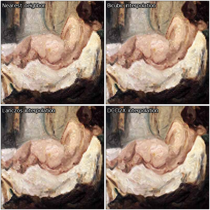
Here are some examples and comparisons of what I get with this new upsizing algorithm:
The filter have been put in the Repair/ section of the G’MIC plug-in for GIMP:
<img src="/uploads/default/original/1X/a48e8f2c7349c41e12f0a0c2c7c5868404dd6f86.png" width=“690”
And here are a few results for x4 upscaling:
height=“409”>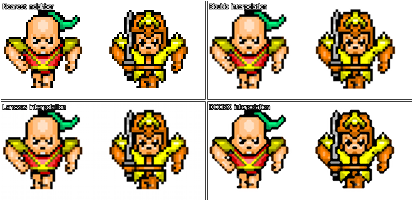


3 Likes
I was playing with this and had a thought.
Instead of interpolating between values, it would be better to estimate the sub-pixels that would make up each pixel if the image had been downsized.
So I came up with this to improve the dcci upscaling, or perhaps it is better called something like ‘targeted sharpening’.
--scale_dcci2x[0] $1,$2,1
--resize[1] [0],2
-sub[2] [0]  # find the differences between the original and the half-sized upscaled version.
-scale_dcci2x[2] $1,$2,1  # upscale the differences
-mul[2] -1
-add[2] [1]  # add them together
-rm[1]

# repeat but with image rotated 180 degrees to remove slight directional bias

-rotate 180


--resize[1] [0],2
-sub[2] [0]
-scale_dcci2x[2] $1,$2,1
-mul[2] -1
-add[2] [1]
-rm[1]

-rotate 180  # rotate back

-c 0,255

2 Likes
Hello
Great stuff in here!
I just wanted to ask that when you show demonstrations of what the algos can do, that you also use them on images which don’t suffer from JPEG compression artifacts. All of the photos from David’s previous post have such artifacts which makes the upscaling demonstration void, at least as far as I’m concerned (though of course some people will upscale JPEGs).
Hello! Suppose I want to upscale an image by 2.3x. Would it be then beneficial to use a DCCI-like method for 2x upscaling and then some other method like Lanczos or “no halo” for the additional 1.15x?
Thanks for providing all that!
Could be maybe better to do x4 first (two passes of dcci2x), then downscale to x2.3 afterwards.
Thanks! I’ll experiment with that as soon as I manage… as a bonus, with photoflow I should be able to provide 8x or even 16x DCCI upscaling with a negligible memory footprint, if that might interest you.
@Iain
Thought you might be interested in this one! That works quite well, although I do notice it re-introduces some “stair-stepping”. What you might want to try tweaking is the smooth/textured pixel part:
 _scale_dcci2x_smooth : -skip ${3=5}
 # calculate interpolated output for smooth areas
 -^[0,1] $3 -+[0,1] 1 --+[0,1] -/[0,1] [-1] -rm. # weights
 -pass$1 -pass$2 -*[0,-2] -*[1,-1] -+[0,1] # smooth
If you override that (obviously only in your own user file!) you can decide what happens to pixels in “smooth area” i.e. weak edges/textures. For example, to simply discard weights and just use 50% of each direction:
 _scale_dcci2x_smooth : -skip ${3=5}
 -f 0.5
 -pass$1 -pass$2 -*[0,-2] -*[1,-1] -+[0,1] # smooth
_scale_dcci2x_smooth is called with two images containing d1 and d2 summed absolute gradients from the algorithm, then passed the interpolated values as another two images:
[0] = d1, [1] = d2 initially
then after -pass$1 -pass$2:
[3] = downright/vertical interps, [4] = upright/horizontal interps
Hope I’ve explained that properly!
1 Like
I tried to implement DCCI myself but I have some problems. You mentioned that the description on Wikipedia is incorrect and the weights should be flipped when interpolating smooth areas. I did that but it still seems to be wrong:
Original:
http://puu.sh/ljsxW/0b197dbe52.png
Upscaled:
http://puu.sh/ljsxD/0e06c1f274.png
The edge looks jaggy and in the corners there are “stray pixels”. Of cause it could just be a bug, but I’ll get some sleep before I try to find out what causes that. I replicate the outer edges by the way. To be more precise: I use the nearest valid pixel when a pixel outside the bounds is being accessed. Also I calculate the edge weights by taking the average across all channels (except the alpha channel, because for now the images I use are always going to be completely opaque).
Do you have some example images? Original and upscaled with DCCI. And I don’t mean the ones posted here in previous replies, I mean plain png-files.
Also you refered to a paper. What paper is that? Where can I find it?
The paper is included (plus test png images) with the matlab example linked as a citation at the bottom of the wiki: http://www.mathworks.com/matlabcentral/fileexchange/38570-image-zooming-using-directional-cubic-convolution-interpolation
For smooth areas you want to interpolate mostly in the direction of the strongest edge, so for the diagonal case:
d1 = up right (45 degree) sum of abs gradients
d2 = down right (135 degree) sum of abs gradients
p1 = interp in up right direction
p2 = interp in down right direction
So if d1 is largest gradient, there’s a stronger edge in the down right direction and we want to interpolate mostly in that direction, so turning gradients into ratios/weights:
w1 = d1 / (d1 + d2)
w2 = d2 / (d1 + d2)
pixel = w1 * p2 + w2 * p1
But of course to deal with division by zero and control edge sharpness by exponent:
w1 = d1^k + 1
w2 = d2^k + 1
weight1 = w1 / (w1 + w2)
weight2 = w2 / (w1 + w2)
pixel = weight1 * p2 + weight2 * p1
The paper suggests using reciprocals to invert them but for ratios there’s no point because:
1/x / (1/x + 1/y) = y / (x + y)
1/y / (1/x + 1/y) = x / (x + y)
Hello. I wrote the Wikipedia article on DCCI. I was looking for information on a good image scaling algorithm, and came across DCCI, then thought it was amazing, then wrote the article.
Sorry if I messed up and made mistakes, if you need the images corrected or anything let me know.
On another note, there’s also another great scaler out there, called Waifu2x. It’s intended for Anime art or line drawings, and it’s incredibly impressive. It’s probably the best scaler I’ve ever seen, but it is extremely slow, taking minutes to run while DCCI takes milliseconds. There’s also an NVIDIA-only version which can scale within 10 seconds rather than minutes.
2 Likes
Aha! Thanks for writing the wiki article, without it I wouldn’t have given the method a second glance - the images convinced me to give it a try.
If we want to stick exactly to the paper there isn’t much wrong but please double check what I say - after having worked with it I know exactly why errors can easily occur!
Smooth area diagonal should read:
Output Pixel = UpRightPixel * weight1 + DownRightPixel * weight2
and likewise for smooth area horizontal/vertical:
Output Pixel = HorizontalPixel * weight1 + VerticalPixel * weight2
The only other difference to the paper is that the horizontal/vertical pass uses a 5x5 kernel rather than 7x7 (see Fig. 4)
Some other things to note:
The paper uses reciprocals but that’s redundant if you simply swap the values.
For colour images, calculating absolute gradient sums for each channel then averaging them produced best PSNR in my own tests, but I’m no scientist so needs confirmation.
If I remember anything else I’ll be sure to add later
1 Like
Just want to again say this is the best uprez method that I’ve come across (to Pat; using Opera to post since Iron Browser’s obviously the issue for me anyway). 
1 Like
Hello !
Sorry this topic is a bit old but I could contribute.
I’m a software developer (and photo is a hobby). I developed this upscale too based on the same wikipedia page.
The method is good to preserve edge and also to prevent aliasing but it failed to retain small details which can be present in picture like photography. The details seems to be distorted by the edge (noticeable in the painting and the red bouy).
I managed to reduce this artifact by increasing the size of the pixel bloc from 4x4 to 6x6 to compute edges and I associated the 5x5 resulting absolute differences with weights.
The weights in the center are heavier than the weight in the border causing better transitions.
Best regards,
PS : Illustration of the gradient computation:


Weights are Binomial coefficients, “Gaussian like” and the sum of the matrix is a power of two good for division
PPS : Please excuse me if my english is poor ^^