Reptorian G'MIC Filters

Since the property of the driving algorithm is periodic, it is important to know what it is for each pattern or colour when plugged into the circle map equation. This happens when

A better analogy than clocks is vibration, say, of grains of sand on a platter, or eddies/waves in fluids like air or water. If the motion is irregular or starting and stopping, there is no perceptible pattern; but as we agitate the particles at a certain frequency, patterns begin to emerge. So we have to figure out what makes the mesmerizing patterns happen for any given combination of Ω and K and other forms of them.

I think I found the answer, but it’s in Python - Example renderings of the chaotic Circle Map. - Details: https://www.patreon.com/posts/24826459 · GitHub

Right there, it say recurrence which I was looking for.

That is the maker of one of the videos on the page you shared on the other forum. Although it is in Python, it is written in a way that is easy to translate into G’MIC script.

Well, it didn’t seem to work:

rep_arnold_tongue:
1000,2000,1,1,"begin(
 const maxiter=max(abs($1),1);
 const ww=w-1;
 const hh=h-1;
 const sd=max(ww,hh)/min(ww,hh);
 const sx=w>h?sd:1;
 const sy=w>h?1:sd;
 const dpi=pi*2;
 const pi_h=hh/dpi;
 const ang_vel=.003;
 circlemap(iter_phi,angle_motor,K)=iter_phi+angle_motor-K*sin(dpi*iter_phi);
);
px=x/ww;
phi=px*sx;
K=(hh-y)/pi_h*sy;
iter_phi=.5;
repeat(maxiter,v,
 iter_phi=circlemap(iter_phi,ang_vel,K);
 if(int(iter_phi*sx)==int(px),break());
);
v;
"

I think I’ll try to translate the python code entirely to see if that’ll work.

@afre

Can you confirm a bug with this code? Looks like position is nan, but yet if I remove the last line in fill, position is 0. What a bizarre bug. Remove the #comment# after you read it.

$ i transparent_image.png new_rep_sptbwgp_shift_horizontal ,,-1,-50%
new_rep_sptbwgp_shift_horizontal:
skip "${1=}","${2=}"

#$1==channel#
#$2==tolerance#
#$3==position#
#$4==influence_factor#

if narg($1)
 sh {$1%s}
else
 sh {s-1}
fi

cond=>0

if narg($2) if $2 cond=>={min($2,iM#-1)} fi fi

100%,100%,100%,{s#0}

1,{h#-2},1,1,:sum([crop(#-2,0,y,z,0,w#-1,1,1,1)]$cond)

f. :"begin(
  const max_index=w#-2-1;
  const shift_position=1+$3;
  print(shift_position);
 );
 num_of_pixels=i;
 pixel_position=0;
 new_pos=int(shift_position*(max_index-num_of_pixels)); #Removing this fixes nan output for shift_position, but it shouldn't end up on nan to begin with#
"

I fixed it by separating the last line of fill, but I still think this is a bug.

Also, this: Strange Output · Issue #251 · dtschump/gmic-community · GitHub

I don’t quite understand what is going on. As usual, I think you need to elaborate a bit more before I can help. Especially the issue entry, it doesn’t look like a complete bug report.

This looks wrong:

cond=>0

if narg($2) if $2 cond=>={min($2,iM#-1)} fi fi

@afre

This is the relevant part of the code.

const shift_position=1+$3;
print(shift_position);

If you insert -1 as $3, then shift_position is nan.
If you remove the line with comment, then it becomes 0.

Likewise, on the issue report, the output is wrong. 50%+1 is 1.5, not 0.

Also, the code is correct. cond is a string, and gmic parse string as code to use on JIT compiler.

1 This first part is okay. No nans unless your input is a nan.

> gmic sp tiger foo
# [gmic_math_parser] max_index = 749
# [gmic_math_parser] shift_position = 0

foo : skip ${1=-1}
  f. :"begin(
      const max_index=w#-2-1;
      const shift_position=1+$1;
      print(max_index);
      print(shift_position);
    );"

2 Careful with percentages: 50% doesn’t have any meaning in your example. The result is 0 probably because 0 means false.

I’ll keep in mind of the percentage though I find it odd that my old rep_sptbwgp stop working as it should (that’s why you see the replacement for it).

More tests: Tiled Zoom stop working too. Never mind. This works. Probably was a false alarm all this time.

So far, I have this on Arnold’s Tongue.

Based on this information Linas has gave me:

Hi Reptorian,

Sorry to take so long to respond. I think you are referring to the poincare recurrence time picture. The pseudocode is this:

for fixed pixel (fixed K, phi):
iterate 150 times; // for good luck, to “settle down and get started”
start_phi = iter_phi; // record the starting angle
count = 0; // count number of loops
for each iteration:
count = count + 1;
if (abs(iter_phi - start_phi) < 0.001) stop iterating
pick color based on count:
if (count < 20) black;
if (count < 100) blue;
if (count < 500) green;
etc.

So basically, its “how long before it comes back (close enough) to the beginning?” You might get a smoother picture with tricks like this:

recur = 0;
for each iteration up to maxiter:
if (abs(iter_phi - start_phi) < 0.001) recur = recur + 1

color = recur / maxiter;

That should work. Apparently, one gets slightly different results if one then averages over different starting angles, or something like that.

The “settle down” phase – I’m not quite sure what happens if you skip it. If I recall correctly, its needed in order to have a point be captured in an attractor (if its ever going to be captured - some points never are) – orbits have a finite-length chaotic sequence, followed by a regular, repeating sequence. It might be interesting to try to measure the length of that initial chaotic sequence. (by “orbit”, I mean the sequence of iter_phi – I’m not sure how much mathematical sophistication you have)

Current code of Arnold's Tongue
1000,2000,1,1,"begin(
 const maxiter=max(abs($1),1);
 const ww=w-1;
 const hh=h-1;
 const sd=max(ww,hh)/min(ww,hh);
 const sx=w>h?sd:1;
 const sy=w>h?1:sd;
 const dpi=pi*2;
 const pi_h=hh/dpi;
 const start_phi=.5;
 circlemap(iter_phi,angle_motor,K)=iter_phi+angle_motor-(K/dpi*sin(dpi*iter_phi));
 fmod(a)=a-floor(a/1.000001);
);
phi=x/ww*sx;
K=(hh-y)/pi_h*sy;
iter_phi=start_phi;
recur=0;
repeat(maxiter,
 iter_phi=fmod(circlemap(iter_phi,phi,K));
 if(abs(iter_phi-start_phi)<.01,recur++;);
);
recur;
"

EDIT:

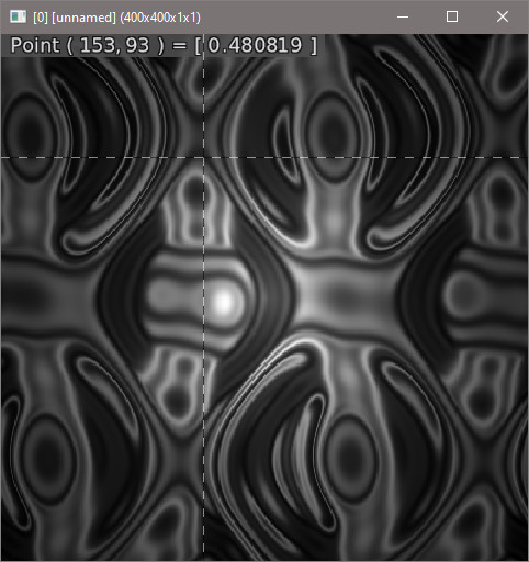
I think I got it, but it seem to require a lot of computation power.

image

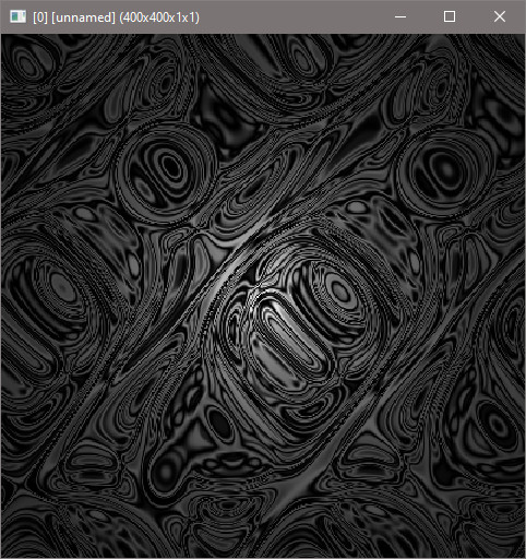
More iterations, and lower cutoff value gives me something more to what Linas picture show.

Yes, the code looks more alike the algorithm now and the pseudo-code for it. I thought it would be quite simple for you to implement but you went about it in a roundabout way. And yes, your commands require more computational power than my laptop can afford; so unfortunately, I cannot test them. Graphically, it still isn’t there but with a few tweaks and considerations I believe you can pull it off.

I don’t think it’s possible to lower the computation requirement. The next e-mail exchange with Linas, I saw that Linas said that it takes him 4-5 days to compute with a 24 core computer. So, I’m just gonna leave the code here for anyone that finds this useful for scientific processing. The code I believe is correct. Same formula as the one in Linas page.

rep_arnold_tongue:
skip ${3=1}
#$1=iteration#
#$2=cut_off_limit#
#$3=sublevel

ww={w}
hh={h}
sub={1+abs($3)}

{w*$sub},{h*$sub},1,1,:"begin(
 const maxiter=max(abs($1),1);
 const ww=w-1;
 const hh=h-1;
 const sd=max(ww,hh)/min(ww,hh);
 const sx=w>h?sd:1;
 const sy=w>h?1:sd;
 const dpi=pi*2;
 const pi_h=hh/dpi;
 const start_phi=.5;
 
 circlemap(iter_phi,angle_motor,K)=iter_phi+angle_motor-K*sin(dpi*iter_phi);
 fmod(a)=a-floor(a);
 
 const cut_off=fmod(abs($2));
);
phi=x/ww*sx;
K=(hh-y)/hh*sy;
iter_phi=start_phi;
recur=0;
repeat(maxiter,v,
 iter_phi=fmod(circlemap(iter_phi,phi,K));
 if(abs(iter_phi-start_phi)<cut_off,recur++;);
);
recur;
"

r. $ww,$hh,100%,100%,6 rm..

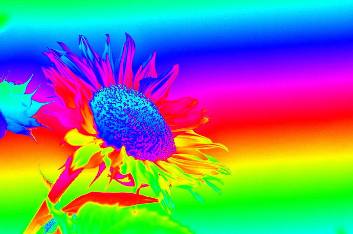
I added a small filter named Rainbowify. Not too much of anything, and there could be improvement in fact. I think I know what to do to improve it. The output looks like this:

Original Source Code in here - jblog: post 180

I’ll add the URL into the g’mic filter itself, but not really feeling it for now.

3 Likes

I fixed a long-standing bug with Construction Material Texture. There is one more thing to do, get rid of background color texture as it does absolutely nothing, and replace it with seed. Done.

1 Like

Just a word on this:
Operator % has two meanings :

  • a%b means a modulo b.
  • a% means a/100.

So, 10%+1 means 10 modulo 1, not 0.1+1.
Add parentheses to disambiguate the cases: (10%)+1.

1 Like

note to self : Do use (1+$1) instead, and (($1)+1) when needed.

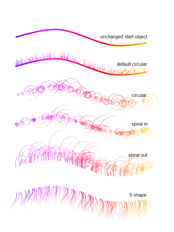
Another note, figure out parametric equations for a new fur blur filter. These for examples are made with parametric equations:

Imgur

So, what I would need to do is to find parametric equations. And extract pixels to set in the fur. On the fur part, I’d imagine that to do it in G’MIC, I would need to either create a 1D vector that is a 2D representation, and rotate it, and then clear it or use a temporary image to generate the parametric curve. Then use draw to plug it on each point.

Now, I had pushed the new version of Diffusion Limited Aggregation. As you can see in the commit, lots of changes. - Upgrade to Diffusion Limited Aggregation · dtschump/gmic-community@11b2ab7 · GitHub


8/1/2021 5:?? PM
Now, I seem to getting somewhere with a better multi-threaded version of rep_dla though I had to do code generation on the fly to do dynamic array and constants on different threads, that part was not enjoyable to code at all. Also, with this, it’s really so much harder to debug. The earlier versions took 2+ mins. This one just takes 3 s-15 s, and that is really a improvement.

Improved Multi-threaded Diffusion Limited Aggregation
$ 500,500 rep_new_dla 3,10,0,0,5

rep_create_alternating_coordinates_map:
1,1,1,2
eval[0] ${-math_lib}"!((x%2==0)!=(y%2==0))*((x%2==0)||(y%2==0))?dar_insert(#-1,[x,y]);
end(resize(#-1,1,dar_size(#-1),1,s(#-1),0););
"
k.
rep_new_dla:
skip ${1=2},${2=10},${3=1},${4=0},${5=0},${6=1}

#$1==_point_proximity#
#$2==_escape#
#$3==aggregation_mode#
#$4==_target={ 0=dark | 1=light }#
#$5==_border#
#$6==_keep_erase_mask={ 0=maskless | 1=mask }#

__bg={$4?0:1}

m "dla_target_2s : n 0,1 s. c * midpoint={avg(iM,im)} f. i>$midpoint?1"
m "dla_target_3s : n 0,1 s c add / 3 midpoint={avg(iM,im)} f. i>$midpoint?1"
m "dla_target_4s_plus : n 0,1 ts={s-1} s c add[^-1] /.. $ts * midpoint={avg(iM,im)} f. i>$midpoint?1"
m "dla_target : if s==1 n 0,1 elif s==2 dla_target_2s elif s==3 dla_target_3s elif s>3 dla_target_4s_plus fi"
m "dla_check_variance : tv=0 repeat s sh $> tv+={iv#-1} rm. if $tv break fi done u {$tv?1:0}"
m "dla_clear_image : {w#0},{h#0},{d#0},1,$__bg rv[-1,0] rm."

if abs($1)>1 m " dla_create_coordinate_map : +rep_noise_poissondisk_to_coordinates {abs($1)} round."
else m "dla_create_coordinate_map : +rep_create_alternating_coordinates_map"
fi

if $4 m "dla_expand : if $5!=0 +dilate_circ[0] {abs($5)} fi"
else m "dla_expand : if $5!=0 +erode_circ[0] {abs($5)} fi"
fi

n_threads={$_cpus}
mt={$n_threads-1}

l. 
 $n_threads,1,1,2
 +s. x
 store[^0] dla_ref
endl

length_const_line=""
dar_lines=""

length_const_line.=begin(
length_const_line.="const ww=w#0;"
length_const_line.="const hh=h#0;"
length_const_line.="const " length_const_line.=lim_atmp=$2;
length_const_line.="const " length_const_line.=dlmode={($4%2)>0?1:0} length_const_line.=;
length_const_line.="const " length_const_line.=use_border="$check_count";
length_const_line.=use_border?(
 repeat $n_threads
  insert_ref_pos={2+$n_threads+$>}
  length_const_line.=check_and_insert_point_$>()=(i(#0,I(#$insert_ref_pos,0,refpos))!=i(#-1,I(#$insert_ref_pos,0,refpos)));
 done
length_const_line.=):(
 repeat $n_threads
  insert_ref_pos={2+$n_threads+$>}
  if $4 length_const_line.=check_and_insert_point_$>()=(i(#0,I(#$insert_ref_pos,0,refpos))<1?1);
  else length_const_line.=check_and_insert_point_$>()=(i(#0,I(#$insert_ref_pos,0,refpos))>0?1);
  fi
 done
length_const_line.=);

repeat $n_threads
 
 insert_dar_pos={$>+2}
 insert_ref_pos={2+$n_threads+$>}

 length_const_line.="const v"
 length_const_line.=$>=
 length_const_line.=h#$insert_ref_pos
 length_const_line.=;
 
 dar_lines.=x==
 dar_lines.=$>
 dar_lines.=?(
 dar_lines.=repeat(v$>,refpos,
 dar_lines.=if(check_and_insert_point_$>(),dar_insert(#$insert_dar_pos,I(#$insert_ref_pos,0,refpos)););
 dar_lines.=);
 dar_lines.=do(n=0;
 dar_lines.=do(
 dar_lines.=temp_vec=I(#$insert_dar_pos,0,n);
 dar_lines.=xp=temp_vec[0];
 dar_lines.=yp=temp_vec[1];
 dar_lines.=if(
  if $4%2
   if $3==0 dar_lines.=(i(#0,xp-1,yp-1,0,0,0,2)||i(#0,xp-1,yp+1,0,0,0,2))||(i(#0,xp+1,yp-1,0,0,0,2)||i(#0,xp+1,yp+1,0,0,0,2))
   elif $3==1 dar_lines.=(i(#0,xp-1,yp,0,0,0,2)||i(#0,xp+1,yp,0,0,0,2))||(i(#0,xp,yp-1,0,0,0,2)||i(#0,xp,yp+1,0,0,0,2))
   elif $3==2 dar_lines.=((i(#0,xp-1,yp-1,0,0,0,2)||i(#0,xp-1,yp+1,0,0,0,2))||(i(#0,xp+1,yp-1,0,0,0,2)||i(#0,xp+1,yp+1,0,0,0,2)))||((i(#0,xp-1,yp,0,0,0,2)||i(#0,xp+1,yp,0,0,0,2))||(i(#0,xp,yp-1,0,0,0,2)||i(#0,xp,yp+1,0,0,0,2)))
   elif $3==3 dar_lines.=altern?(i(#0,xp-1,yp-1,0,0,0,2)||i(#0,xp-1,yp+1,0,0,0,2))||(i(#0,xp+1,yp-1,0,0,0,2)||i(#0,xp+1,yp+1,0,0,0,2)):(i(#0,xp-1,yp,0,0,0,2)||i(#0,xp+1,yp,0,0,0,2))||(i(#0,xp,yp-1,0,0,0,2)||i(#0,xp,yp+1,0,0,0,2))
   fi
  else
   if $3==0 dar_lines.=(i(#0,xp-1,yp-1,0,0,0,2)<1||i(#0,xp-1,yp+1,0,0,0,2)<1)||(i(#0,xp+1,yp-1,0,0,0,2)<1||i(#0,xp+1,yp+1,0,0,0,2)<1)
   elif $3==1 dar_lines.=(i(#0,xp-1,yp,0,0,0,2)<1||i(#0,xp+1,yp,0,0,0,2)<1)||(i(#0,xp,yp-1,0,0,0,2)<1||i(#0,xp,yp+1,0,0,0,2)<1)
   elif $3==2 dar_lines.=((i(#0,xp-1,yp-1,0,0,0,2)<1||i(#0,xp-1,yp+1,0,0,0,2)<1)||(i(#0,xp+1,yp-1,0,0,0,2)<1||i(#0,xp+1,yp+1,0,0,0,2)<1))||((i(#0,xp-1,yp,0,0,0,2)<1||i(#0,xp+1,yp,0,0,0,2)<1)||(i(#0,xp,yp-1,0,0,0,2)<1||i(#0,xp,yp+1,0,0,0,2)<1))
   elif $3==3 dar_lines.=altern?(i(#0,xp-1,yp-1,0,0,0,2)<1||i(#0,xp-1,yp+1,0,0,0,2)<1)||(i(#0,xp+1,yp-1,0,0,0,2)<1||i(#0,xp+1,yp+1,0,0,0,2)<1):(i(#0,xp-1,yp,0,0,0,2)<1||i(#0,xp+1,yp,0,0,0,2)<1)||(i(#0,xp,yp-1,0,0,0,2)<1||i(#0,xp,yp+1,0,0,0,2)<1)
   fi
  fi
 dar_lines.=,
 dar_lines.=i(#0,xp%ww,yp%hh)=dlmode;
 dar_lines.=dar_remove(#$insert_dar_pos,n);
 dar_lines.=n--;
 dar_lines.=attempts=0;
 dar_lines.=);
 dar_lines.=n++;
 dar_lines.=,n<dar_size(#$insert_dar_pos));
 dar_lines.=repeat(dar_size(#$insert_dar_pos),p,
 dar_lines.=temp_vec=I(#$insert_dar_pos,0,p);
 dar_lines.=px=temp_vec[0];
 dar_lines.=py=temp_vec[1];
 dar_lines.=pv=round(u(0,7));
 dar_lines.=npx=newpos_x[pv];
 dar_lines.=npy=newpos_y[pv];
 dar_lines.=I(#$insert_dar_pos,0,p)=[px+npx,py+npy];
 dar_lines.=);
 dar_lines.=,dar_size(#$insert_dar_pos)&&(attempts<lim_atmp));
 dar_lines.=)
 
 if ($>!=$mt) 
  dar_lines.=:
 else
  dar_lines.=;
 fi
 
done

length_const_line.=newpos_x=[-1,-1,-1,0,0,1,1,1];
length_const_line.=newpos_y=[-1,0,1,-1,1,-1,0,1];
length_const_line.=);
length_const_line.=attempts=0;
length_const_line.=altern=round(u(1));

echo $length_const_line
echo $dar_lines

repeat $! l[$>]
 dla_create_coordinate_map
 
 dla_check_variance[0]
 use_dla_map=${}
 
 echo $use_dla_map
 
 l[0] $dla_ref endl
 
 s. y,$n_threads
 
 ti={$!}
 check_count=0
 
 if $use_dla_map
  dla_target[0]
  dla_expand
  check_count={$!-$ti}
 else
  dla_clear_image
  set[0] {1-$__bg},50%,50%,{d#0==1?0:50%}
 fi
 
 eval[1] :${-math_lib}$length_const_line$dar_lines
endl done
1 Like

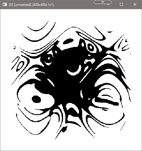
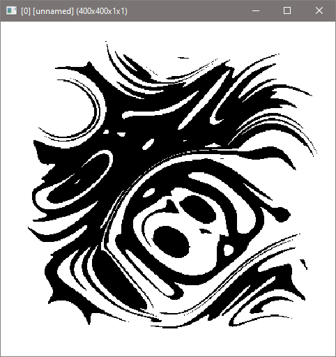
Thanks to @weightt_an code, I will be creating a new filter based on his code. Some of the interesting results:

image

image

image

image

2 Likes

I’ll be leaving my user.gmic file right here as I’ll be away from my main PC in a while -
user.zip (14.2 KB) . Makes it easier to gmic elsewhere.

I’m back to my main PC. Only have gotten a bit more progress on fixing map projection code. That being said:

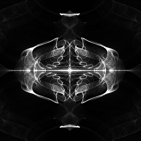
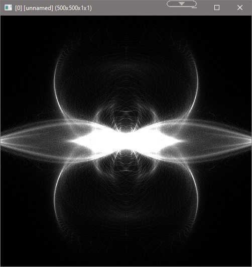
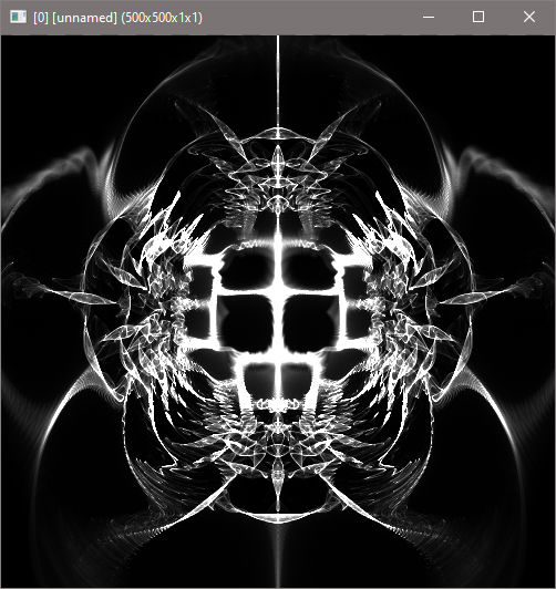
I haven’t replicated complex Popcorn Fractal, but I did managed to get interesting images:


EDIT:

I finally got somewhere with making my dream filter:

Yes! Thanks to finally figuring out that norm in c++ is different than in g’mic.

Another test:

Now, I managed to get custom formulas (You won’t see them in the document I used for development of this script):

5 Likes