I have been working on something interesting within vkdt, and now that it is working fairly okay already, thought I’d mention this here too in case someone wants to test/take a look.
The idea here is that we create a lut from a camera ssf that maps the camera rgb to sigmoid coefficients given the scene illuminant. The lut generation uses much of the existing vkdt infrastructure, expanding a bit for this new format.
This lut is then evaluated in an rgb-to-spectral module that allows choosing the illuminant temperature, exposure, etc. The image is then output as a 40-channel radiance payload, and can be connected to downstream modules that support this format. Thus, we can work on the reconstructed spectral data with no rgb roundtrips.
There is also a version of the filmsim module that has been stripped of rgb math, cat adaptations and such, and works directly on this spectral input (it no longer needs its own spectral upsampling either).
Then, to go back to rgb for display/output, we have a spectral-to-rgb module that takes in the 40-channel payload, integrates it against a chosen cie observer, and outputs rec2020 rgb.
The memory requirements of this format are a bit absurd though, as we are using a 40-channel format as the transport instead of the usual 3 .
The temperature slider evaluates different points of the lut, similarly to how it works in the colour modules clut-based camera->rec2020 transformation!
If I understand this correctly, doing it this way should be more accurate, because we can encode different spectra for the same camera rgb values at different illuminant temperatures
absolutely crazy i mean we could re-compress the spectra to some more economical intermedate representation. of course introducing compute overhead.
i’ve seen moments used for this purpose (can be computed directly from spectrum, reconstruction is a bit heavier), or rgbe-style data (8-bit values at seven wavelengths + shared exponent for all values).
but without starting from crazy-shaped spectra i’m not sure how much we’d lose by using rgb → spectrum → rgb → spectrum iteratedly, processing spectrum and storing rgb. the upsampling should round-trip with the projection… only the processing might throw this off manifold.
that said, i’d like to explore an upsampling table with more than 3 coefficients and match it to andrea’s PCA spectra. might avoid the heavy data load and still generate some more interesting shapes / more accurate fits to foliage and skin.
Honestly testing this thing its not even all that horrible, filmsim in this spectral path is around 100ms (350ms → 450ms) slower on my laptop compared to the version in the filmsim pr, and vram usage with a 40mp image jumps from ~3gb to ~5gb
Thinking about your last point, would a less smooth-shaped spectral reconstruction like this introduce more loss if we do rgb<->spectrum round-trips? I am also wondering about what actually happens after processing the spectra with for example the filmsim module and packing it to rgb, and upsampling back to spectra? It seems like we should at least lose some information in this process (of course whether we lose information that is visually interesting is another thing, probably depends on if we just want to do the film simulation, or if we would want to chain up many different operations that depend on the spectra)
gpus are such bandwidth monsters… but yeah, that’s one extra spectral buffer now. and while the memory allocator will alias buffers if it can… i don’t think that scales to very complex graphs.
yeah now the rgb → sigmoid spec is 3D → 3D so pretty unique of a mapping. using more coefficients and going to rgb i’d lose some definition, certainly. and upsampling i’m not sure makes much sense to optimise against rgb, i’d optimise it against spectral shapes directly. for those kinds of spectra i’d certainly expect some loss when going to rgb as intermediates. need to try and store these extra coefs with low bit counts. they normally don’t compress so well and need f32.
Thanks! Any step in this direction would be huge. I’ve been complaining about the limits of ICC profiles and the lack of support for dual-illuminant DCPs in dt in this forum more than once, I think.
What you’re describing pretty much sounds like dual-illuminant DCPs? However, with them one does not have to “make a profile for any illuminant just by calling it out in make-profile with ‘-i D65’ ”. That interpolation between the two illuminants happen on-the-fly. Sorry for poisoning this thread with my limited understanding.
To make a dual-illuminant DCP with dcamprof, you need to make two single-illuminant profiles, then tell dcamprof to make the dual-illuminant one with the matrices from the two single-illuminant profiles. Like this (some parameters and steps omitted for clarity):
Oh, can’t help you there, except you can make scene-specific ICC target profiles. Or, use RawTherapee, which groks DCPs.
Frankly, not worth the effort to chase, IMHO. You should be able to easily determine the dominant color temperature of a shot, then use a camera profile made for that illuminant. Most of my photography is in daylight or roughly equivalent flash, so a D65 profile is what I use by default. Haven’t experimented with a StdA profile, but I easily could with SSF data.
You can use the matrices printed by the make-profile command inside a compositing software like Natron or Gaffer, they’re both open source free alternatives to Nuke.
Apply the matrices to an exr for example and see the results.
Natron/Gaffer both support OpenColorIO, so you can create a 3dlut and use it in Darktable.
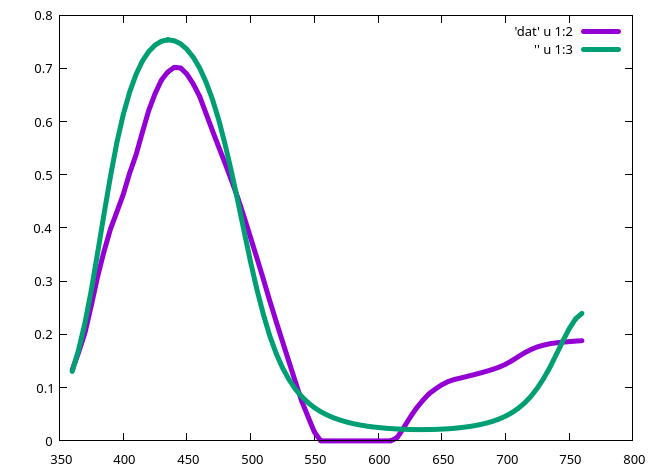
some progress on GPU-happy spectral upsampling with spectral shapes from examples. made a fitter work on example spectra, fitting a sigmoid(polynomial()) model with more than 3 polynomial coefficients. this one is with 8:
(purple is the data, green is the fit. the usual 3 coefficients would not be able to express both the peak and the dip and the same time)
i was planning to fit this against arctic’s pca spectra so i have a hole-free coverage of spectra for the whole xy-plane. also might be able to reduce the lut resolution a bit and use interpolation instead. storing 8 values instead of 81 might do the rest. will need some refinement/post processing to match the reference xy coordinates perfectly after the approximation data → model.
Not sure if this is the right thread. But the basic question/ idea is: why is spektrafilm modelling film only with 3 channels? I know there are the Spektrum-based in-and-out conversions using 81 channels, but why is the film chemistry itself (like the DIR couplers) only modelled with 3 channels?
Typical colour negative film (like Portra) has 8 layers: 2 blue,3 green and 3 red, being ordered from fast to slow. (BF,BS,GF,GM,GS,RF,RM,RS) And there are at least two good reasons to model them separately.
DIR couplers work on physical proximity. So Let’s say we have DIR coupler release in the green layers. This should affect the slow blue layer slightly more than the fast blue layer. And in the red layer, in reverse, the fast red layer should be more affected than the slow red layer.
The spectral response of large grains and small grains is different. Large grains in the fast sublayers feature expansive, flat, defect-free (111) or (100) crystal facets. Because the crystal surface is flat and uniform, organic cyanine dye molecules adsorb cleanly into long-range, highly ordered J-aggregates. Coherent exciton coupling across these ordered dye rows narrows the absorption band into a sharp, high-efficiency J-peak. Slow sub-layers consist of tiny, highly curved micro-crystals. These small grains have a high proportion of surface steps, corners, and crystal edge defects. Because the surface is highly curved and irregular, dyes cannot form long-range, uninterrupted J-aggregates. This creates a creates a much broader, multi-peak spectral absorption envelop.
Basically, slow sublayers have broader spectral response, which leads to less colour separation and saturation.
Therefore, I propose to model the film actually in 8 channels instead of just 3.
I slopcoded my own simulation, and it works well, but I am in no position to contribute this, as the code is not validated at all.
Per my understanding there is not enough data available that would allow modeling all these details. The data published by the film manufacturers seems to mostly be limited to 3 channels.
Do you happen to have some measured data that would help in improving the model in this regard?
Would surely also be interested to take a look at what you have come up with regarding your own simulation if you would be comfortable sharing that!
I am currently trying my luck with non ideal setup but the fact I managed to make a DCP that looks somewhat better than the flat desaturated embedded matrices on my pixel made me happy. I am using a tiny black box with a piece of a CD. Getting a CFL where I live was hard because even online sellers cancelled the order for some reason then I found a whole box of them at an old shop.
I started finding light sources with known SPD for measurements with distinct peaks and it was so nice to look at the tech world around me with a new perspective. I found what part of spectrum the LEDs lack (making it so trashy for this) . The neon bulb inside line tester screwdriver, halogen headlights of my bike (which is probably coated to absorb some of the cooler side making my current DCP a bit…muddy and inaccurate).
Now I am hoping to give up my laziness and setup everything as recommended for the best results I can find for less than $5 of investment (I got a 15 W CFL for $1 and I already had many CDs.)
I should probably move this over to your 4 post series which was so amazing that I finally had to try it myself as a side project to keep me excited every day!
Thank you @ggbutcher for all the help you’ve shown with both direct answers and everything else you’ve contributed.
For the spectral response I am currently still working on a model that “sharpens” the response in the fast layers and “softens” it in the highlights but respects the average spectral response. Currently it’s just what looks artistically good without proper measurements behind it.
For the DIR couplers however there is enough data to make it accurate. You already model the Diffusion process. And the Diffusion process across layers with source and sink is the same. The total layer height is around 15μm thick with emulsion layers being 1-1.5μm each and intermediate layers being 0.2-0.5μm. Just that instead of a 2D diffusion process now a 3d diffusion process has to be modeled.
Oh, when I wrote those four posts I remember thinking, ‘who’d be crazy enough to replicate this?’, Ha, now I know…
I just skimmed the arvix paper, interesting to find they used LED illuminators to map the pixels to the appropriate wavelengths. That might be an improvement on my use of separate spectrum/calibration illuminators, you’d need a separate SPD of the specific LED illuminator to bias-out the energy discontinuities. I might have to test this…
 .
.

 i mean we could re-compress the spectra to some more economical intermedate representation. of course introducing compute overhead.