So it looks like your PTFE-sheet is the most
neutral, followed by the Porta Brace WBC.
But what bothers me are the values you get from
the Spyder Checkr’s “card white” patch.
Its values are published as (sRGB) 249/242/238
and (aRGB) 247/242/237 — which in your case points
into the directon of improper exposure and/or some
biased light source…
I think with DT you can have the best of both worlds…if you have a card then you can use the color checker mode of the C C module and get a fairly accurate WB and exposure as they are evaluated. As you point out the white on the Spyder card is a bit warm so if you use it on its own you might actually overcorrect your images…Doing scene referred edits in my mind you just need a nice neutral reference … gray or white so that you can set WB…so in that case the Porta looks good. BP and WP are relative and more fluid than what you might see with a display referred edit…so to me a “white” patch for exposure is less important
I’m afraid it’s a case of me being unscientific. I set the white balance for the entire image by sampling the Porta Brace. I then used the colour picker’s right click to select similarly sized squares from the other other items. The photo was taken outdoors in cloudy northern England at 9.40 a.m.
If I base the white balance on the Spyder, then its white square will have equal RGB values and everything else will be off. If I base the white balance on the yellowing eraser that I wrapped PTFE around, then it too will have equal RGB values.
Probably best if I upload the RAW file for you to play with…
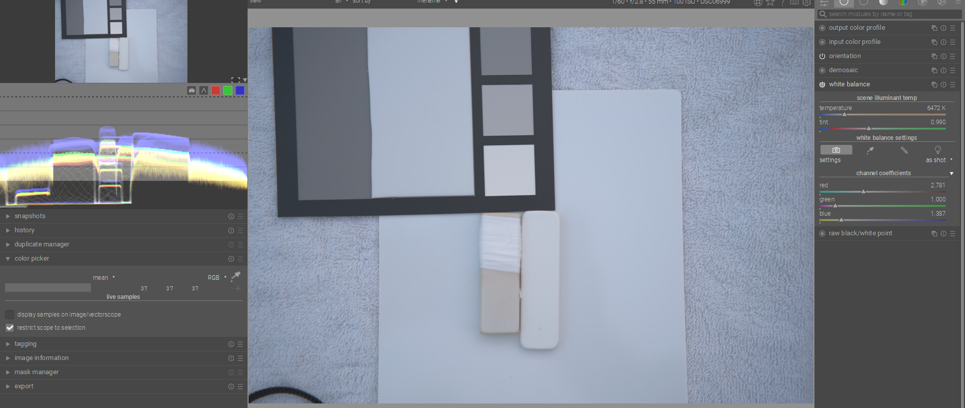
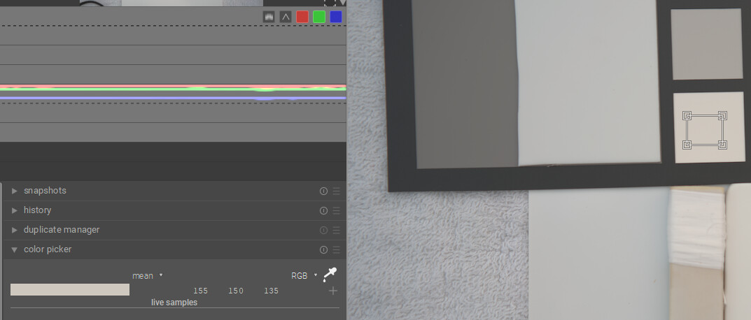
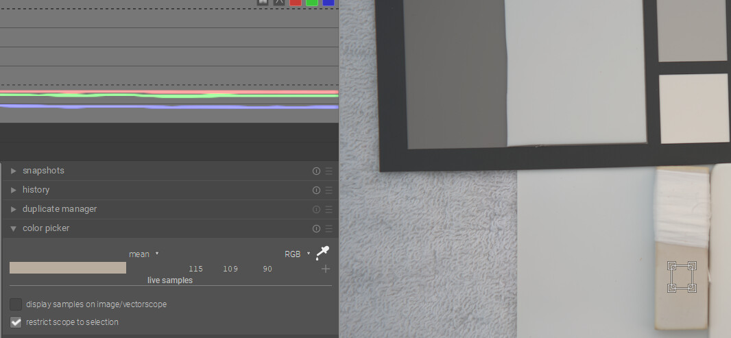
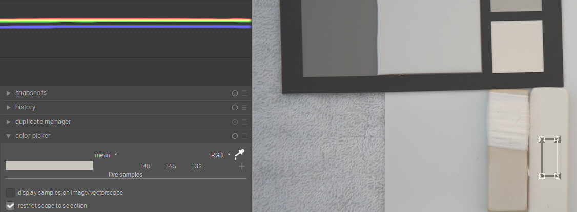
Now make sure you select restrict to selection in the picker and using the waveform you can compare relative sources and see which are the most neutral…
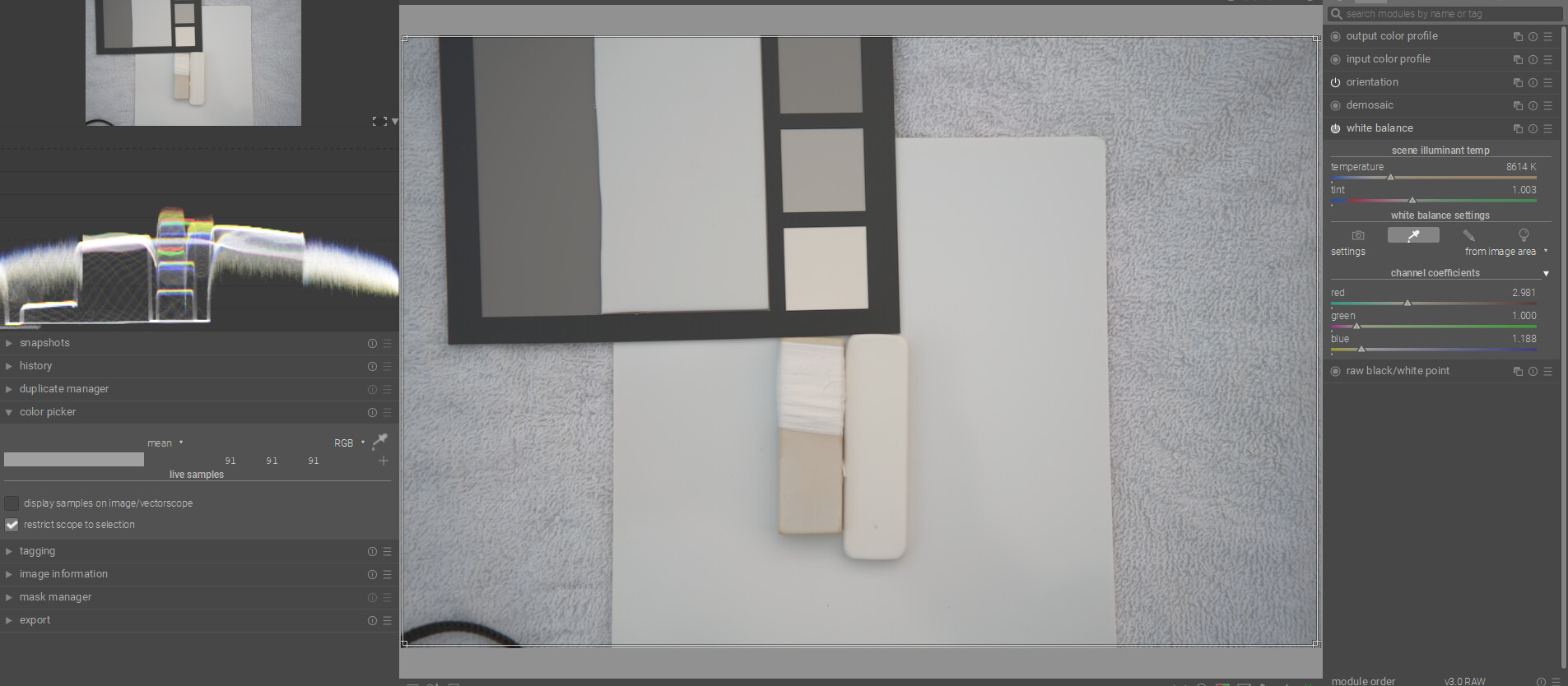
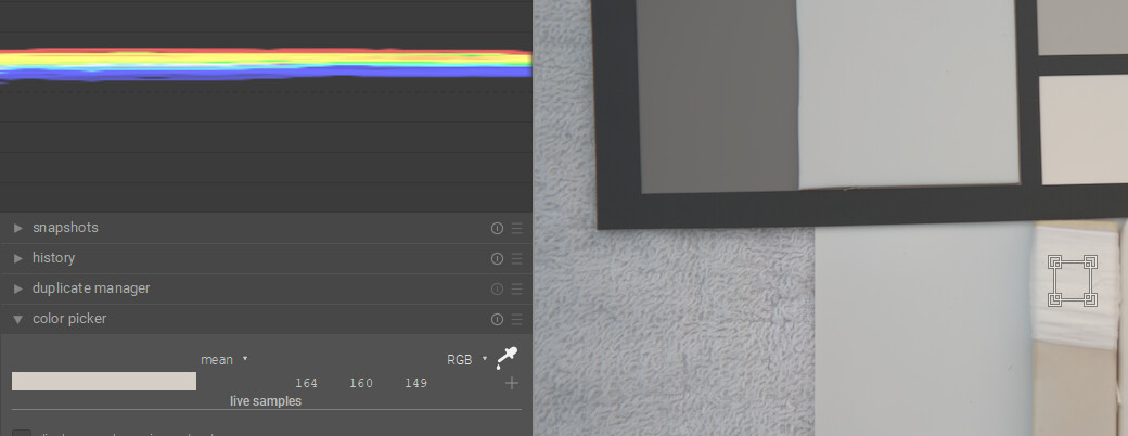
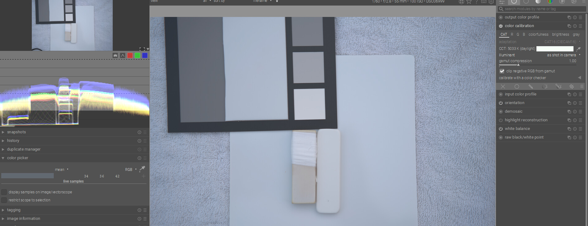
You can now switch that to camera reference and then enable color calibration and try that…repeating the same steps …you can also save the samples if you are curious
CC starts here for as shot… as you can see the “K” values are not really similar even though you are seeing the same result…this is what I was talking about wrt values in the CAT space.
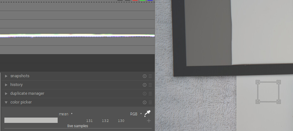
You can make that same selections and look at the waveform…white indicates overlap of the channels and so more neutral and then not neutral you will see the channels spread apart in the waveform…
So if it is a neutral white the PTFE and the PortaBrace seem the most neutral…
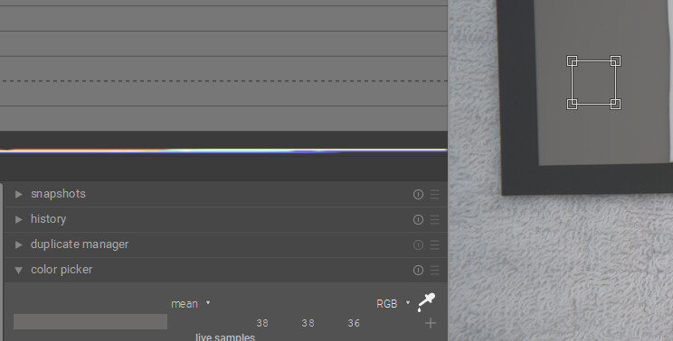
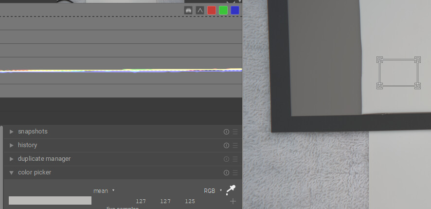
Sample 1 is the grey patch sample 2 the PTFE and Sample 4 Porta Brace…
The image is a bit dark but I don’t think a bump will change that outcome…
At least this is how I would take a quick look at it to compare some different ones…