Hello Alberto,
are you kidding? … in a simple way?
Yes, there’s probably no easier way to explain why and how Log Tone Mapper works in just a few minutes.
I see the great effort you have made, but for me the numbers are and remain an unsolved mystery:
“black relative exposure” is -13.5, and 0.18 * 2^{-13.5} \approx 00.18∗2−13.5≈0 …
I fear, or hope, that I am not the only one who finds this far too mathematical.
But you didn’t do all this for nothing. I think I have a good understanding, especially because of the video, of what shifting the gray point and the white point means.
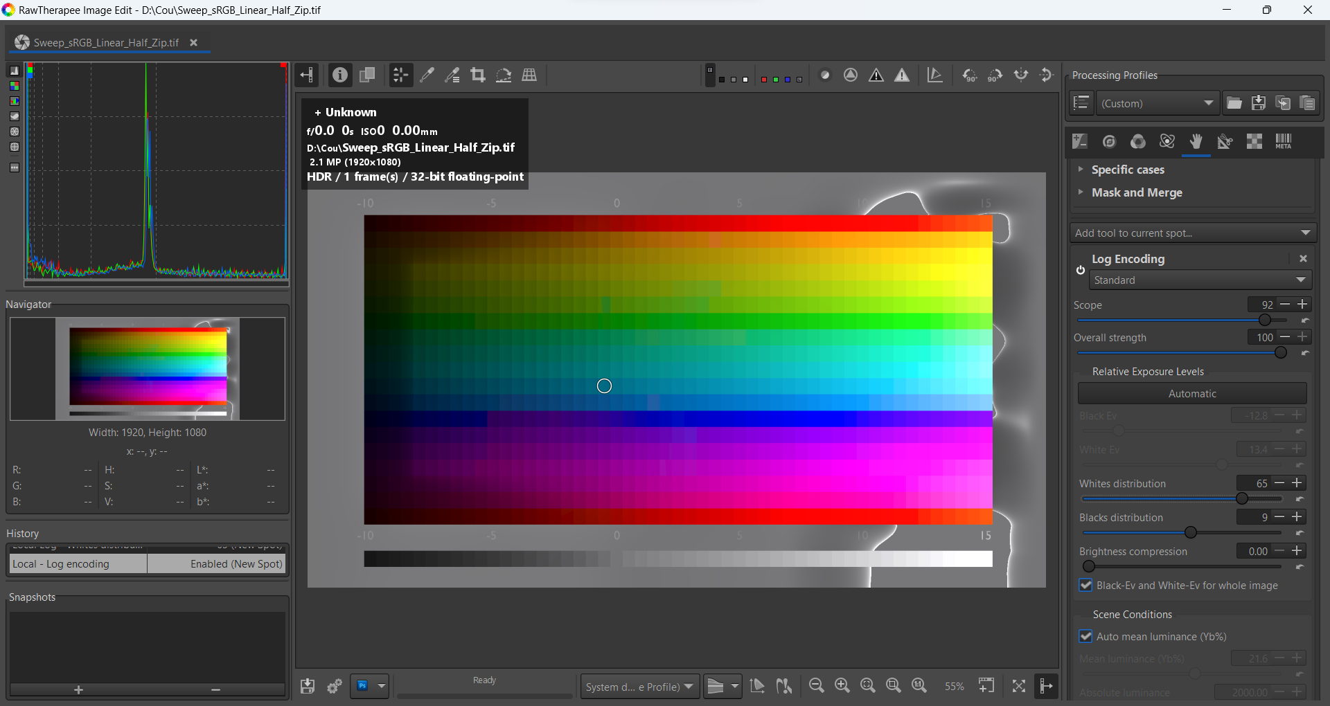
What an interesting graphic mid.tif is: It normally contains a lot of white, and with ART (also with Gimp), you can change the tonal values so that the white is gradually drawn again.
I have translated your text into German and copied it into my private ART-manual. I will read it more often and make sure that I understand more bit by bit.
Alberto, you have already made a short video about LTM, albeit in an older version of ART.
1st request: Could you make a video of the development with LTM with a suitable picture?The whole world of ART will certainly thank you.
2nd request: Could you describe in more detail which images give LTM an advantage over other tools such as Tone Equalizer? Or can you achieve the same results with Tone Equalizer as with LTM?
I’m probably only going to expose my shortcomings but this is a non-technical summary of how I interpreted @agriggio’s explanation:
The lightest linear / unbounded value is mapped to bounded (display) white, or 1
The darkest linear / unbounded value is mapped to bounded (display) black, or 0
The “balance” of the grey (gradient) slope between these two values is determined by where the Target gray point slider is positioned.
I.e., using the two equations he provided, the brightest and darkest points are mapped to (display) white and black, with the center grey point being relatively set by the Target gray point slider. He’s basically remapping white and black relative to the Target gray point slider value.
I think one thing right off the bat you could use is the jpg. If its still got deep shadows, bright sky etc then you know it has been tone mapped and processed and still it has DNR issues… Then to use the raw and to manage that and produce a better result your likely going to benefit from the Log tone mapper…
I think also when you look at the Tone eq map … it does appear that the “zones” are nicely feathered generally and I don’t exactly know how they are determined however if you hunt and peck with sliders in the tone eq you might sort of break the image tonality where as the tone mapping (with filmic or this sort of module) is a global edit with smooth gradients and can be used to capture (compress) the dynamic range and set you up for further processing… some of which might be the tone eq to fine tune things…
Hello Alberto,
I very much hope I haven’t upset you. My poor head, which is already 69 years old, is smoking. But for some reason I want to know.
I’ve watched your video over and over again and especially studied your text. Now I understand the two important controls: target gray point and white relative exposure pretty well.
And I took your “recipe, for most images” to start with target gray point to heart. And look: it works very well. For this picture I only use: Target gain +50, Gain -2 and with Tone Equalizer I make the sky a little darker and the result is very fast, just as I imagined.
I just want to tell you not to be annoyed if it takes me so long to understand.
Your efforts are bearing fruit. And for that I thank you and everyone who was involved.
I am sorry if you didn’t understand something. That’s not what triggered me, I just took your reply in the wrong way, and I apologise. I did my best trying to explain how the tool works, and yes, this includes a little bit of math. I tried to keep this at a minimum, and in my view it was more like an extra, the video explanation would have been the main point.
Anyway, it’s all good now!
I am glad that we were able to clear up the misunderstanding.
I never questioned the quality of your explanation. I just realized that the way it works is too “high” for me and I understand so little about these numbers.
I just wanted to know how to apply log tone mapping. It was my mistake for asking how it works - there’s a big difference.
The video was very descriptive, but your text is hugely important to me because now I understand much better what the sliders do. This makes it much easier for me to see what they do in practice, I know what I have to pay attention to in order to see and understand the effect.
It has clarified a lot and now I have enough knowledge to practice and gain my own experience with it.
It’s not the lightest, it’s just the user selected value. The tool doesn’t clip anything, and brighter tones can still be compressed later (e.g. by a lut or by the new “base curve” options in the tone curve).
For me, “Target gray point” changes the mid tones the most, but also the dark tones and the black. Only the white remains untouched. Is that different for you?
It’s not different, it works the same here. But it does not change the black point for you either. In your screenshot, the black point is set to be 13.5 stops below mid gray (that’s what “-13.5 Ev” means in the GUI), but the darkest band in the test picture is only 10 stops below mid gray. If you set “black relative exposure” to -10, you will see that the darkest band will stay at zero no matter what value you set for “target gray point”.
Hello @jonathanBieler
I don’t know if this is the right way, maybe you want to know something completely different: But I manage to make all white levels visible with RT, just with “Dynamic Range Compression” > Amount > Maximum = 100.
I may be missing something but aside from reading the tools’ absolute values out of the sidecar (arp) we can’t tell anything without the raw file. We need both to really see what’s happening.
That said, a few points:
If at all possible try some kind of lens profiling, whether from LensFun (auto or manual) or from an LCP file.
Make sure you’re not double-correcting for CA. Both Profiled Lens Correction (Transform tab) and Chromatic Aberration Correction can potentially correct CA. But if they’re both enabled it can overcorrect. For my lenses, I’ve found the Raw CA tool works better than even the custom LCP profiles I made with the Adobe Lens Profile Creator. Who knows – Maybe I just did a poor job on the LCPs…
The Defringe tool (Detail tab) and correct for fringing beyond what CA tools can do, across the color spectrum. Just be careful to not introduce artifacts.
It’s theoretically possible to use the Local Adjustments Color/Tone Correction tool with a finely tuned Color Similarity mask to mitigate this but it would be a last resort for me.
@micha@jonathanBieler
I modified (a little) the code of “LA Log encoding” and “LA Cam16” (when Log encoding is activated in Pre-Ciecam).
From scope = 50, “ΔE scope threshold” and “ab-L balance (ΔE)” are modified internally, as well as the reduction of deltaE. Maximum effect since scope=90.