A question reg behavior of the color correction mosaic in RT Dev (Appimage 3075)
The color adjustment mosaic in the Color Toning filter seems to allow making adjustments by moving the pointer which has its root fixed at the center - Fig-1.
A similar (or same) color adjustment mosaic in the local adjustments/Color&Light seems to behave differently in that the root of the pointer itself is movable - Fig 2.
I am guessing that in Fig-1 the fixed center point may be representing the original state of colors in the mask created. If that is indeed the case, what does the movement of the base of the pointer (as seen in Fig-2) mean?
(Please excuse my choices of words, I feel I have struggled to find correct words to ask this question, apologies if I have used wrong terms. Hope the figures are explanatory )
The two examples you gave do very different things. One is based on RGB (the Colour Correction Regions) and the other is based on the a and b channels from L*a*b (Colour Correction Grid).
The Colour Correction Regions basically changes the whole image to a certain colour (assuming no masks are dialled in) when moving the white dot/handle.
The Color Correction Grid in the Local Adjustments → Color & Light tool uses the black dot as target colour and the white dot as new colour.
I get the impression that you know how to work with the colour toning module, so here’s a basic/simple example what you could do with the Color Correction Grid:
As you can see in this example you can selectively change red to blue and green to purple (or any colour to another colour).
Wow… this is certainly something I should learn. Thanks @Jade_NL - as always - for the explanation and excellent video help. Much appreciated
RGB vs LAB color model… Hmm… I should have noticed the “L-a-b standard” label just above the Grid for a clue. I will do that first to better appreciate this powerful feature.
My initial understanding - The black dot helps create an (unseen/internal) mask which is modified to the color position of the white dot? Is that right?
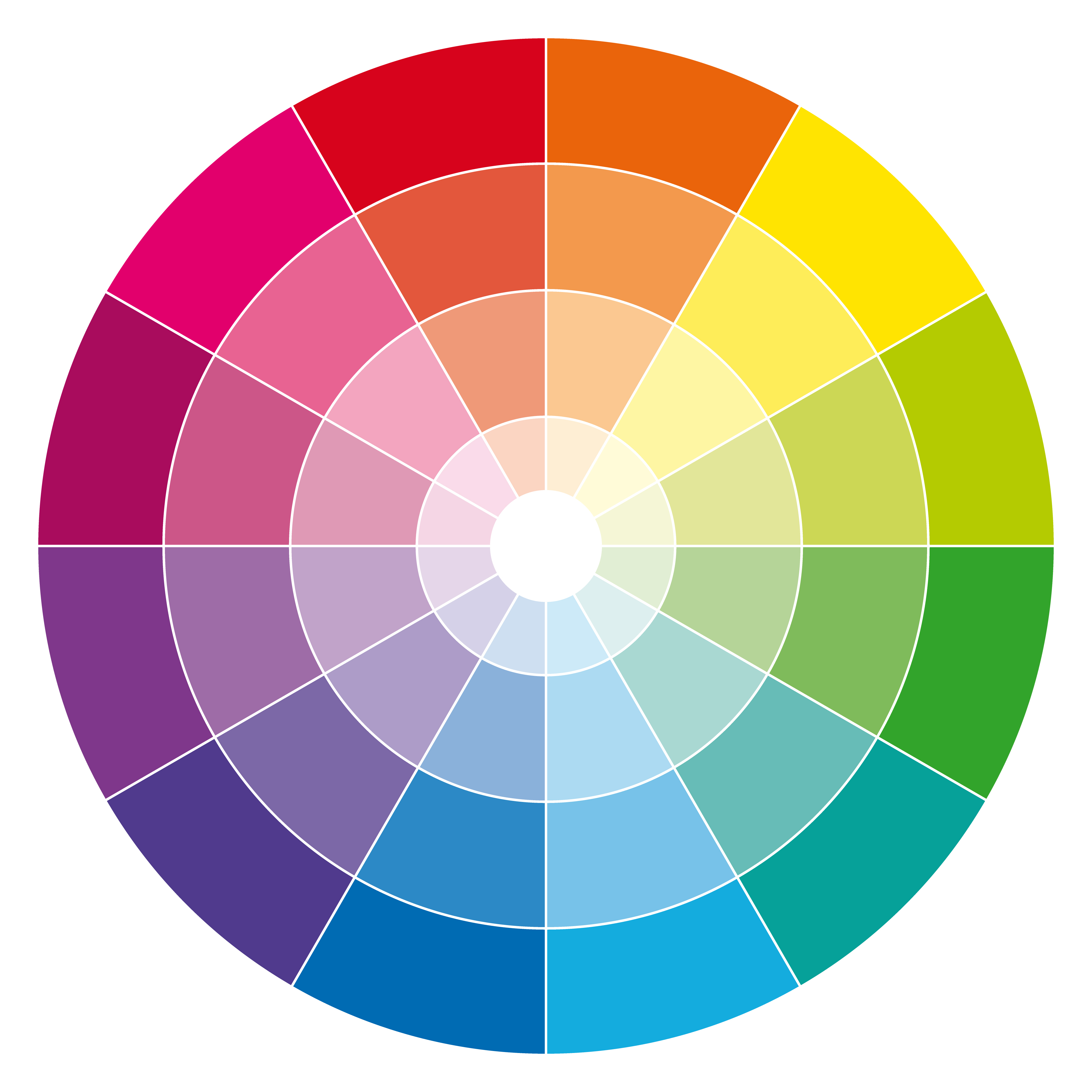
The white dot represents the a channel and adds/removes these colours (magenta<->green), the b channel does this for blue ->yellow.
The masking, not shown in the above video, is done the normal way and can be fine tuned using the scope and Shape detection sliders. As you can see in the above video there’s spillover to the adjacent colours. This is due to the fact that I did not dial in the specific mask using the scope/shape detection. I left the defaults as-is.
Maybe I might have described it somewhat wrongly by saying target colour for the black dot and new colour for the white dot. Setting the black dot on the target colour makes it possible to add/subtract blue(/yellow) and the white dot adds/subtracts magenta(/green).
Here’s another video, showing a bit of basic masking and the effect that the b channel has on the selection:
EDIT
Setting lockable colour picker(s) set to L*a*b might help.
I will now explore this grid further with the following limited objective that I often have to set for myself while touching up images – “make minor changes to the shades of colors that appear in the original image”. If I am able to create local adjustment mask(s) on those areas and find out what their original LAB values are using the lockable picker, I could use the color correction grid to alter the L,A or B values slightly such that the desired colors appear.
 )
)
