Try the pattern → mosaic filter for g’mic-qt. See if you like the structure. That may be the solution.
1 Like
You are a genius, I have no idea why I didn’t think of that!
Here’s what I’ve come up with:
jr_mosaic 20,15,10%

jr_mosaic:
repeat $! l[$>]
+gradient_norm b. $3 n. 0,1
100%,100%,100%,2,'u<0.25*(lerp($1%,i(#1),$2%))^4?[u,1]' s. c
distance. 1 *. -1  watershed.. . rm[1,3]
blend shapeaverage
endl
done
The second and third options allow the size of the segments to adjust to the level of detail in the original image.
1 Like
I like the simpler code. If you could combine the chunks to make more deliberate intersecting shapes, and chose more primary, complimentary and opponent colours; then you would be done. 
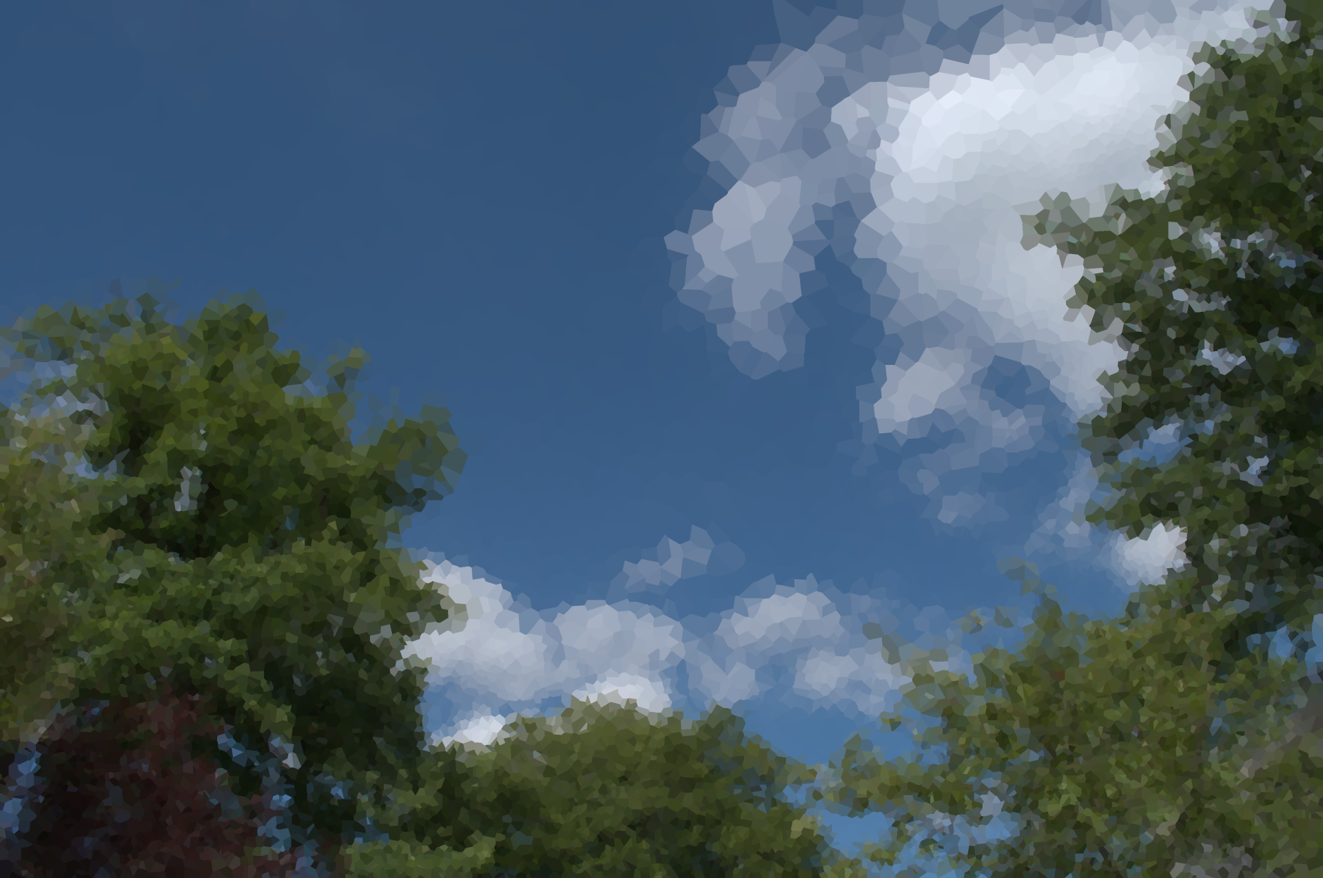
Hold on, the borders of those mosaic pieces in that image are smooth! How did you do that? Was that with a post-processing anti-aliasing thing?
Anyway, I now have two filters to sort out then: the cubism one and the previous jumbling thing. One of the ideas I have for the new cubism mosaic thing involves using gradients within each segment. I should also generate some edges…
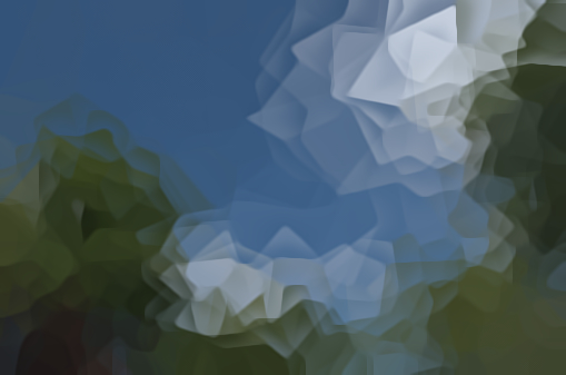
So here’s something I made from that:
#@gui Multi-Mosaic: fx_jr_multi_mosaic_preview
#@gui : sep = separator()
#@gui : 0. Recompute = button()
#@gui : 1. Iterations=int(3,1,10)
#@gui : sep = separator(), note = note("<small><b>Mosaic</b></small>")
#@gui : 2. Density=float(15,0,100)
#@gui : 3. Details Influence=float(15,0,100)
#@gui : 4. Details Smoothness=float(0,0,100)
#@gui : sep = separator(), note = note("<small><b>Smooth [Diffusion]</b></small>")
#@gui : 5. Iterations=int(16,0,100)
#@gui : 6. Sharpness=float(0.5,0,2)
#@gui : 7. Anisotropy=float(1,0,1)
#@gui : 8. Gradient Smoothness=float(3,0,10)
#@gui : 9. Tensor Smoothness=float(5,0,10)
#@gui : 10. Time Step=float(15,5,50)
#@gui : sep = separator(), note = note("<small><b>Edges [Gradient Norm]</b></small>")
#@gui : 11. Opacity=float(1,0,1)
#@gui : 12. Smoothness=float(0,0,10)
#@gui : 13. Linearity=float(0.5,0,1.5)
#@gui : 14. Min Threshold=float(0,0,100)
#@gui : 15. Max Threshold=float(100,0,100)
#@gui : 16. Negative Colors=bool(0)
#@gui : sep = separator(), note = note("<small><b>Final Edge Blend</b></small>")
#@gui : 17. Edge Blend=bool(1)
#@gui : 18. Smoothness=float(15,0,100)

fx_jr_multi_mosaic:
repeat $! l[$>]
repeat $1 +l[0]
+gradient_norm n. 0,1 b. $4
100%,100%,100%,2,'u<0.25*(lerp($2%,i(#1),$3%))^(4)?[u,1]' s. c
distance. 1 *. -1  watershed.. . rm[1,3]
blend shapeaverage
smooth. ${5-10},0
+fx_gradient_norm ${12-16} *. $11
split_opacity..
-[^1]
a c
endl done
rm[0]
if $17 blend_edges $18 fi
endl done

fx_jr_multi_mosaic_preview :
fx_jr_multi_mosaic ${2-19}
fx_jr_multi_mosaic 3,31.3,42.7,0,20,0.594,1,1.73,3.25,7.925,0,0,0.5,0,100,0,1,8 on this image:
…gives me this:
Edit: a few changes. Now it can do multiple densities at once.
New script
#@gui Multi-Mosaic: fx_jr_multi_mosaic_preview
#@gui : sep = separator()
#@gui : 0. Recompute = button()
#@gui : 1. Iterations=int(3,1,10)
#@gui : sep = separator(), note = note("<small><b>Mosaic</b></small>")
#@gui : 2. Lowest Density=float(15,0,100)
#@gui : 3. Highest Density=float(45,0,100)
#@gui : 4. Details Influence=float(50,0,100)
#@gui : 5. Details Smoothness=float(0,0,100)
#@gui : sep = separator(), note = note("<small><b>Smooth [Diffusion]</b></small>")
#@gui : 6. Iterations=int(16,0,100)
#@gui : 7. Sharpness=float(0.5,0,2)
#@gui : 8. Anisotropy=float(1,0,1)
#@gui : 10. Gradient Smoothness=float(3,0,10)
#@gui : 11. Tensor Smoothness=float(5,0,10)
#@gui : 12. Time Step=float(15,5,50)
#@gui : sep = separator(), note = note("<small><b>Edges [Gradient Norm]</b></small>")
#@gui : 13. Opacity=float(1,0,1)
#@gui : 14. Smoothness=float(0,0,10)
#@gui : 15. Linearity=float(0.5,0,1.5)
#@gui : 16. Min Threshold=float(0,0,100)
#@gui : 17. Max Threshold=float(100,0,100)
#@gui : 18. Negative Colors=bool(0)
#@gui : sep = separator(), note = note("<small><b>Final Edge Blend</b></small>")
#@gui : 19. Edge Blend=bool(1)
#@gui : 20. Smoothness=float(15,0,100)

fx_jr_multi_mosaic:
to_rgba
repeat $! l[$>]
repeat $1 +l[0]
+gradient_norm n. 0,1 b. $5
100%,100%,100%,2,'u<lerp(0.5,i(#1),$4%)*((lerp($2,$3,($>/max(1,($1-1))))*0.01))^4?[u,1]'  s. c
distance. 1 *. -1  watershed.. . rm[1,3]
blend shapeaverage
smooth. ${6-11},0
+fx_gradient_norm ${13-17} *. $12
split_opacity..
-[^1]
a c
endl done
rm[0]
if $18 blend_edges $19 fi
endl done

fx_jr_multi_mosaic_preview :
fx_jr_multi_mosaic ${2-20}
@Joan_Rake1 I should let you know that your .gmic file was edited in github as part of code cleaning effort.
Okay, that was easy to sort out because it was mostly about replacing tab stops with spaces.
So this more cubist command is done and it’s got loads more features, but now I’ve still got the problem of the original ‘cubist’ one’s anti-aliasing…
Multi-Mosaic
#@gui Multi-Mosaic: fx_jr_multi_mosaic_preview
#@gui : sep = separator()
#@gui : 0. Recompute = button()
#@gui : 1. Iterations=int(3,1,10)
#@gui : sep = separator(), note = note("<small><b>Mosaic</b></small>")
#@gui : 2. Lowest Density=float(15,0,100)
#@gui : 3. Highest Density=float(45,0,100)
#@gui : 4. Details Influence=float(50,0,100)
#@gui : 5. Details Smoothness=float(0,0,100)
#@gui : 6-8. Colour Balance=color(128,128,128)
#@gui : 9. Luma Range = float(0,0,100)
#@gui : 10. Chroma Range = float(0,0,100)
#@gui : 11. Hue Range = float(0,0,100)
#@gui : sep = separator(), note = note("<small><b>Edges [Gradient Norm]</b></small>")
#@gui : 12. Opacity=float(1,-1,1)
#@gui : 13. Smoothness=float(0,0,10)
#@gui : 14. Linearity=float(0.5,0,1.5)
#@gui : 15. Min Threshold=float(0,0,100)
#@gui : 16. Max Threshold=float(100,0,100)
#@gui : 17. Thickness=int(1,1,10)
#@gui : 18-20. Color = color(0,0,0)
#@gui : 21. Luma Range = float(0,0,100)
#@gui : 22. Chroma Range = float(0,0,100)
#@gui : 23. Hue Range = float(0,0,100)
#@gui : sep = separator(), note = note("<small><b>Final Edge Blend</b></small>")
#@gui : 24. Edge Blend=bool(1)
#@gui : 25. Smoothness=float(15,0,100)
#@gui : sep = separator(), note = note("<small><b>Smooth [Diffusion]</b></small>")
#@gui : 26. Iterations=int(16,0,100)
#@gui : 27. Sharpness=float(0.5,0,2)
#@gui : 28. Anisotropy=float(1,0,1)
#@gui : 29. Gradient Smoothness=float(3,0,10)
#@gui : 30. Tensor Smoothness=float(5,0,10)
#@gui : 31. Time Step=float(15,5,50)
#@gui : sep = separator(), note = note("<small><b>Local Normalization</b></small>")
#@gui : 32. Amplitude=float(2,0,60)
#@gui : 33. Radius=int(6,1,64)
#@gui : 34. Neighborhood Smoothness=float(5,0,40)
#@gui : 35. Average Smoothness=float(20,0,40)
#@gui : 36. Constrain Values=bool(1)
#@gui : 37 .Channel(s)=choice(2,"All","RGBA [All]","RGB [All]","RGB [Red]","RGB [Green]","RGB [Blue]","RGBA [Alpha]","Linear RGB [All]","Linear RGB [Red]","Linear RGB [Green]","Linear RGB [Blue]","YCbCr [Luminance]","YCbCr [Blue-Red Chrominances]","YCbCr [Blue Chrominance]","YCbCr [Red Chrominance]","YCbCr [Green Chrominance]","Lab [Lightness]","Lab [ab-Chrominances]","Lab [a-Chrominance]","Lab [b-Chrominance]","Lch [ch-Chrominances]","Lch [c-Chrominance]","Lch [h-Chrominance]","HSV [Hue]","HSV [Saturation]","HSV [Value]","HSI [Intensity]","HSL [Lightness]","CMYK [Cyan]","CMYK [Magenta]","CMYK [Yellow]","CMYK [Key]","YIQ [Luma]","YIQ [Chromas]","RYB [All]","RYB [Red]","RYB [Yellow]","RYB [Blue]")

fx_jr_multi_mosaic:
to_rgba
repeat $! l[$>]
repeat $1 +l[0]
+gradient_norm n. 0,1 b. $5
100%,100%,100%,2,'u<lerp(0.5,i(#1),$4%)*((lerp($2,$3,($>/max(1,($1-1))))*0.01))^4?[u,1]'  s. c
distance. 1 *. -1  watershed.. . rm[1,3]
blend shapeaverage
1,1,1,3,([$6,$7,$8]) rgb2lch8. f. "I+[u(-255,255)*$9%,u(-255,255)*$10%,u(-255,255)*$11%]" lch82rgb.  fx_balance_gamma.. {I(#-1,0,0,0)},0 rm.
+to_rgb.
fx_gradient_norm. ${13-16},0 dilate_circ $17 to_rgba. 1,1,1,3,([$18,$19,$20]) rgb2lch8. f. "I+[u(-255,255)*$21%,u(-255,255)*$22%,u(-255,255)*$23%]" lch82rgb. f.. "[I(#-1,0,0,0),($12<0?255-i0:i0)*abs($12)]" rm.
blend alpha
endl done
rm[0]
if $24 blend_edges $25 fi
smooth ${26-31},0
endl done
fx_normalize_local ${32-37}
fx_jr_multi_mosaic_preview :
fx_jr_multi_mosaic ${2-38}
Found a nice glitch art setting there. Set Lowest Density to 0, and Highest Density to 100. I see a nice line streak.

Other than that, some great mosaic art filter!
That’s an artefact of local normalisation on an image where all pixels are the same value. Setting the density to 0 does that.
I have some ideas regarding the old ‘cubism’ command’s AA: I can go back to using a 2x2 window and use a blurred version of the gradient norm as a blending weight.
Edit: I’ll stick with the distance-to-nearest-edge approach but with a smoothed gradient norm weighting thing instead. I’ve swapped the segmentation for the mosaic thing instead, but still no progress with the AA.
The old 'cubism' command right now
#@gui Cubism: fx_jr_rep_cubism_preview
#@gui : sep = separator()
#@gui : 0. Recompute = button()
#@gui : 1. Density=float(15,0,100)
#@gui : 2. Details Influence=float(50,0,100)
#@gui : 3. X Offset Centre=float(0,-100,100)
#@gui : 4. X Offset Range=float(25,0,200)
#@gui : 5. Y Offset Centre=float(0,-100,100)
#@gui : 6. Y Offset Range=float(25,0,200)
#@gui : 7. Z Offset Centre=float(0,-100,100)
#@gui : 8. Z Offset Range=float(0,0,200)
#@gui : 9. Rot Angle Centre=float(0,-360,360)
#@gui : 10. Rot Angle Range=float(360,0,360)
#@gui : 11. Rot Axis X Centre=float(0,-1,1)
#@gui : 12. Rot Axis X Range=float(0,0,2)
#@gui : 13. Rot Axis Y Centre=float(0,-1,1)
#@gui : 14. Rot Axis Y Range=float(0,0,2)
#@gui : 15. Rot Axis Z Centre=float(1,-1,1)
#@gui : 16. Rot Axis Z Range=float(0,0,2)
#@gui : 17. AA Iterations=int(16,0,100)
#@gui : 18. Sharpness=float(0,0,2)
#@gui : 19. AA Anisotropy=float(1,0,1)
#@gui : 20. AA Gradient Smoothness=float(1,0,10)
#@gui : 21. Tensor Smoothness=float(5,0,10)
#@gui : 22. Time Step=float(15,5,50)


fx_jr_rep_cubism:
to_gray
# initial parameters for all images
rotac=$9
rotar=$10
rotxxc=$11
rotxxr=$12
rotxyc=$13
rotxyr=$14
rotxzc=$15
rotxzr=$16
aa=$17
repeat $! l[$>]
# initial parameters for each image
ww={w}
hh={h}
dd={d}
xoffc=$3*0.01*$ww
xoffr=$4*0.01*$hh
yoffc=$5*0.01*$dd
yoffr=$6*0.01*$ww
zoffc=$7*0.01*$hh
zoffr=$8*0.01*$dd
+gradient_norm
100%,100%,100%,2,'begin(n=-1);u<lerp(0.5,i(-1),$2%)*($1%)^4?(n+=1;[u,1])' s. c
distance. 1 *. -1  watershed.. . rm[1,3]
label.	# labelling the segments of the copied image
l[1]
# get the edges of the segment and find the distance to the nearest pixel on the other side of the nearest edge for each pixel in terms of x, y and z components
# this will be used for the anti-aliasing later on
+gradient_orientation. 3
a[^0] c
100%,100%,100%,1,"min(1,ceil(norm(I(#1))))"

rm[1]
distance. 1
+gradient_orientation. 3
f[1] "-(i+0.5)"  # experimenting with this to find a good distance offset, should really be (i+0.5) for true distance to edge
a[1-4] c

endl
# uncomment this to blur this distance-to-edge image, was just another experiment but could be used to highlight the problem in a clearer way
# b. 2
# approximate the centre of each segment and store the x, y and z components in a new image which will store more parameters later
# this image's x coordinate is the segment id as specified in the labelled segment image (#1)
initsize={1+iM#1}
$initsize,10,1,1
vsize={$initsize*3}
eval ${-math_lib}"
coordinates_per_val=vector"$vsize"(0);
count_per_val=vector"$initsize"(0);
for(px=0,px<w#1,px++,
 for(py=0,py<h#1,py++,
  for(pz=0,pz<d#1,pz++,
   pos=i(#1,px,py,pz);
   coordinates_per_val[pos*3]+=px;
   coordinates_per_val[pos*3+1]+=py;
   coordinates_per_val[pos*3+2]+=pz;
   count_per_val[pos]++;
  );
 );
);
for(n=0,n<"$initsize",n++,
 coordinates_per_val[n*3]/=count_per_val[n];
 coordinates_per_val[n*3+1]/=count_per_val[n];
 coordinates_per_val[n*3+2]/=count_per_val[n];
 I(n,0)=coordinates_per_val[n*3];
 I(n,1)=coordinates_per_val[n*3+1];
 I(n,2)=coordinates_per_val[n*3+2];
);
"
# add pseudo-randomised parameters for each segment id to the parameters image
sh. 3,9,0,0 f. ">begin(randm=u(100,200);randa=u(1,3));srand((x+(randa)+(u))*(randm+y));u(-1,1)"
eval. "begin(multvec=["$xoffr","$yoffr","$zoffr","$rotar","$rotxxr","$rotxyr","$rotxzr"];
addvec=["$xoffc","$yoffc","$zoffc","$rotac","$rotxxc","$rotxyc","$rotxzc"]);
for(n=0,n<w,n++,
strip=crop(n,0,0,0,1,7,1,1);
draw(#4,(strip*multvec)+addvec,n,0,0,0,1,7,1,1,1))"
rm.
# get the edges, subtract a smoothed copy in order to create a mask for the anti-aliasing
+gradient_norm[1] f. "i>0?255:0"
smooth. $aa,${18-22},0
/. 255
# let's put all of this together now
f[0] "critical(begin(const spec=s;aa="$aa";
cubism(id,xx,yy,zz)=( # this function warps a given pixel using the parameters assigned to a specified id within the parameters image
params=crop(#3,id,0,0,0,1,10,1,1);
# get segment centre
xc=params[0];
yc=params[1];
zc=params[2];
# get offsets
xoff=params[3];
yoff=params[4];
zoff=params[5];
# get rotation angle and axis
ang=params[6];
xa=params[7];
ya=params[8];
za=params[9];
# rotate and offset
vx=xx-xc-xoff;
vy=yy-yc-yoff;
vz=zz-zc-zoff;
pix=[xa,ya,za];
select=(rot(asin(pix/norm(pix))*2/pi,ang)*[vx,vy,vz])+[xc,yc,zc];
# return the new pixel value
I(select,1,3)));
# anti-aliasing only if the setting's enabled and we're at a pixel where the mask (#4) has a non-zero value
(aa&&(i(#4)>0))?(
# get the displacements necessary to reach the nearest pixel on the other side of the nearest edge
dist=i(#2,x,y,z,0);
xdist=-i(#2,x,y,z,1)*dist;
ydist=-i(#2,x,y,z,2)*dist;
zdist=-i(#2,x,y,z,3)*dist;
# trilinear interpolation to determine the value of the nearest pixel behind the nearest edge
# we don't have to cubism() eight times for each pixel here since we can instead make a weighted histogram of ids
idlist=vector(#8,-1);
freqlist=vector(#8,0);
idnum=0;
xint=floor(xdist);yint=floor(ydist);zint=floor(zdist);
xo=xdist-xint;yo=ydist-yint;zo=zdist-zint;
gridmult=[(1-xo)*(1-yo)*(1-zo),xo*(1-yo)*(1-zo),(1-xo)*yo*(1-zo),xo*yo*(1-zo),(1-xo)*(1-yo)*zo,xo*(1-yo)*zo,(1-xo)*yo*zo,xo*yo*zo];
for(pz=0,pz<2,pz++,
 for(py=0,py<2,py++,
  for(px=0,px<2,px++,
   curr=i(#1,x+xint+px,y+yint+py,z+zint+pz,0,1,1);
   pos=find(idlist,curr);
   pos==-1?(idnum+=1;pos=find(idlist,-1);idlist[pos]=curr);
   freqlist[pos]+=gridmult[pz*4+py*2+px];
  );
 );
);
val=0; # val=vector(#spec,0);
for(n=0,n<idnum,n++,
# construct the final value for the interpolated pixel
val+=idlist[n]*freqlist[n]);
# interpolate between that pixel and the current one in accordance with the AA mask
lerp(val,i(#1,x,y,z,0,1,1),i(#4))):
# if we don't need any AA, we can just use the current pixel
(i(#1,x,y,z,0,1,1)))
"
# clean up now that we're done
display
rm[^0]
endl done
to_rgb
n 0,255
fx_jr_rep_cubism_preview:
fx_jr_rep_cubism ${2-23}
This is based on the procedure I used to try and get the value of the pixel just beyond the other side of the boundary. It’ll operate on any input image. Why does it only work when I use -(i+n) when n is larger than 1.5?
mosaic ,
label
+l
+gradient_norm f. "i>0?1:0"
distance. 1
+gradient_orientation. 3
f[1] "-(i+1)"
a[1-4] c
f.. "dist=i(#1,x,y,z,0);
xdist=round(i(#1,x,y,z,1)*dist);
ydist=round(i(#1,x,y,z,2)*dist);
zdist=round(i(#1,x,y,z,3)*dist);
J(xdist,ydist,zdist)"
endl
display
Also, is there really any other method that I can use to anti-alias this? I have one more method but it means I have to sacrifice any blurring and focus only on AA. How do I use the output of structuretensors?
If it works when n>1.5, then is it possible to exploit that to solve it by using a conditional?
How would I use a conditional in that case?
I don’t know, really. Maybe based on radial angle? I have no idea how to work with your script.
There’s no reason to care about radial angles. f[1] "-(i+1)" (which should be f[1] "-(i+1.5)" but as usual I messed it up again) just adds 1 to the distance-to-edge calculation before negating it all, and this is used later on in the last f block with the x, y and z components having been given by gradient_orientation.
I still don’t understand this. What does increasing and negating the intensity have to do with modifying the edge?
The resulting ‘intensity’ is actually supposed to be the magnitude of the vector which leads to the nearest pixel behind the nearest edge for any given pixel. I want to selectively blend the values of each pixel with the nearest one behind the nearest edge.

Let’s say that the red pixel is the currently-processed pixel in an f block. The green blob is approximately where the nearest whole pixel on the other side of the edge between the white and grey parts. I need to find that pixel’s value, and to do that I need the offset between the two pixels.
Edit: if this really goes nowhere I’m gonna need a complete alternative. I have something morphological but it’s gonna be a nightmare to implement - I’ll take line segments and turn them into equations with blending weights.
Your snippet generates images[0-2] out of sp tiger. image[1] looks like a shattered version of image[0]. There are overlapping edges and dots inside the shapes. Some of this is black near the boundaries.
image[1] by itself

That’s close to the desired effect - the aim for that snippet is to generate a mosaic and then replace each pixel’s value with the one just behind the nearest edge. The black parts near the boundaries are due to the boundary conditions being Dirichlet instead of Neumann like they are in the old cubism command.
I made this to see what happens to the output when I change certain parameters - it produces a three-channel image where the first channel is a post-label mosaic, the second is supposed to be the value of the nearest pixel behind the nearest edge and the third is the edge for the mosaic.
mosaic ,
label
+l
+gradient_norm f. "i>0?1:0"
+distance. 1
+gradient_orientation. 3
f[2] "-(i+1.5)"
a[2-5] c
f... "begin(boundary=1);dist=i(#2,x,y,z,0);
xdist=round(i(#2,x,y,z,1)*dist);
ydist=round(i(#2,x,y,z,2)*dist);
zdist=round(i(#2,x,y,z,3)*dist);
J(xdist,ydist,zdist)"
endl
f[2] "i*i(#1)*0.5"
rm.
a c
display

So another idea I have is just to smooth the edges by trying to get the values which are along the edges instead of on the other side of the edges. I need to make a map of blending weights and pixel offsets from the gradient orientation. How would I implement this in 3 dimensions though, where I’m also dealing with faces? I know that I can get a 3D map of the gradients, smooth it, and then there’s my map of weights - but how do I know what pixels I need to select? How do I get the distance that a pixel has moved during smoothing?
Edit: before I forget, here’s an edge detection thing I’m gonna try to use…
100%,100%,100%,6,"begin(boundary=1);
val=vector(#6,0);
I(#0)!=J(#0,1)?(val[0]+=1); # right
I(#0)!=J(#0,0,1)?(val[1]+=1); # down
I(#0)!=J(#0,0,0,1)?(val[2]+=1); #in
I(#0)!=J(#0,-1)?(val[3]+=1); # left
I(#0)!=J(#0,0,-1)?(val[4]+=1); # up
I(#0)!=J(#0,0,0,-1)?(val[5]+=1); # out
val"
*. 255
smooth. 16,0,1,1,5,10,0
/. 255
Edit: when I changed my script slightly I thought to myself that I’m doing it all wrong and that instead of setting a pixel’s value based on other pixels around it, I should really be influencing the values of other pixels which aren’t currently selected. I can use the edge orientation to make pixels ‘bleed’ in certain directions. But with either method I don’t know how I’ll weight all the pixel values.
100%,100%,100%,6,"begin(boundary=1);
val=vector(#6,0);
I(#0)!=J(#0,1)?(val[0]+=1); # right
I(#0)!=J(#0,0,1)?(val[1]+=1); # down
I(#0)!=J(#0,0,0,1)?(val[2]+=1); #in
I(#0)!=J(#0,-1)?(val[3]+=1); # left
I(#0)!=J(#0,0,-1)?(val[4]+=1); # up
I(#0)!=J(#0,0,0,-1)?(val[5]+=1); # out
val"
*. 255
smooth. 16,0,1,1,5,10,0
/. 255
f.. "edge=I(#1,x,y,z);"
Coming back here just to stash an idea…
Bézier surface - Wikipedia I could use splines like these to separate patches of an image, but how would I make them conform to patches of an image?
I need either a voxel antialiasing algorithm or a bunch of smooth functions (piecewise or not). I still want to do the 3D antialiasing thing.