Would it be a big problem to add an option of reducing amount of distortion correction applied automatically for a given lens? It could be really useful.
Can you give an example of where it would be useful? I don’t use lens correction all that often, but when I want to use it, I have yet to find a case where I only want partial distortion correction (or partial correction of chromatic abberation).
In any case, I think the actual corrections are done by the lensfun library. So getting a partial correction done would mean
- getting the distortion parameters (is this even possible?(*) ),
- modify them to get a partial correction, and
- get lensfun to do the correction with those new parameters.
I’m not sure you can modify the parameters to do a decent partial correction without knowledge of the model behind the parameters (and lensfun provides for the use of several models…)
(*) There’s no real reason for the library to provide a way to get at the parameters. The application has to provide camera and lens parameters to retrieve the correction values, but as the library does the actual correciton, there’s no need for the application to read the exact correction values. It doesn’t have the corresponding correction model implemented anyway.
In DT 4.4 a new mode has been added to the lens correction module that gets the correction from metadata embedded in the image instead of Lensfun. It currently supports Sony, Fuji, and DNG, and I have been working on adding Olympus support but it’s not done yet.
In this mode there is a slider to ‘fine tune’ the distortion correction. The slider has an effect for Sony, Fuji, and for a DNG that specifies only distortion but not CA correction. It has no effect for a DNG that specifies both distortion and CA correction since they are combined into a single operation and can’t be fine tuned separately.
The distortion correction works by defining a mapping from a radius in the undistorted output image to a radius in the distorted input image. So for every pixel in the output image, it starts at that corresponding pixel in the input image. It then moves along a line drawn from the center of the image to that pixel, toward or away from the center of the image by an amount specified by the correction function, and takes the pixel value at that point. When the distortion fine-tune setting is adjusted away from 1.0, the distance it moves along that line is scaled by the fine-tune setting. I’m not sure if that physically makes sense based on how lens distortion works, but that’s what the code is doing.
1 Like
I noticed that each time distortion correction is applied, there is loss of IQ at edges and in corners. Sometimes less distortion correction would still be sufficient while avoiding too much IQ degradation.
I do not have Sony/Fuji/DNG/Olympus cameras, so cannot try the new feature.
I can understand that it is indeed complex. Anyway, thanks for your feedbacks.
That lensfun uses multiple distortion models doesn’t help. Only the simplest one, the third-order polynomial, has just one parameter controlling the distortion; the others range from two to five, with what I think is the most popular because it’s the hugin model has three.
Lensfun is kinda like a fully-provisioned machine shop where most things are usually done with only the screwdriver and hammer. rawproc use of lensfun just deals with straightforward use of the available corrections in the XML dataset; I might look at what it would take to make a fully-enabled lens correction tool with the available toolset in the master branch…
2 Likes
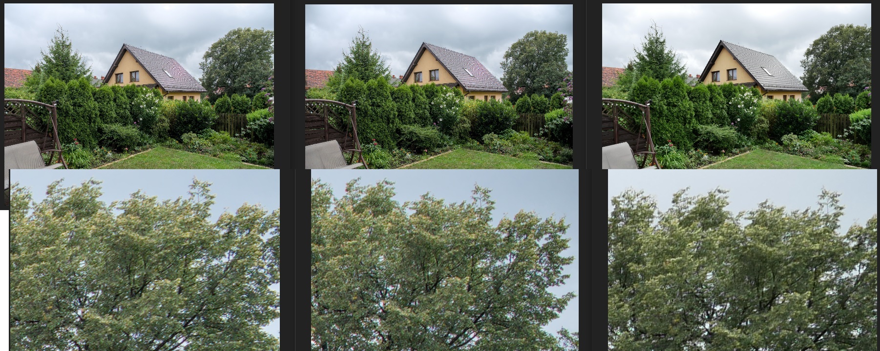
I would like to show you an example related to my original question. I have compared:
- jpg from dt with distortion correction applied (the picture on the left)
- jpg from dt without distortion correction (the picture in the middle)
- SOOC jpg (the picture on the right)
First of all, the non-corrected picture seems most natural to me. The least natural is dt with correction applied. Regarding details, it is the same, most details obviously in the picture without correction, but still SOOC is better than dt with corrections.
Is the distortion correction properly used in dt? Should I fix some values? I used defaults as the camera and lens are automatically detected (m4/3 system).
You can try the different projections to see if you find one you prefer over the default.
You can also turn off geometry correction, but still correct vignetting and CA.
You might also try a different demosaicing algorithm: the “dt” pictures show quite a strong moiré effect in the roof, more than the SOOC image. And the demosaicing also influences the fine detail.
Lens correction isn’t the only difference between the camera treatment and the dt treatment. It looks like the camera applied more sharpening or local contrast than dt, which is a factor that influences perceived detail.
Also the crop looks (slightly) different in dt and SOOC. That can be because the camera has a “default crop” that’s slightly more aggressive than dt’s.
Or the lens correction is applied in a slighty different way (so that pixels are “pushed out” rather than “pulled in”: e.g. barrel distortion required you to “pull in” the edge pixels, “push out” the corner pixels, or use a combination of the two…). That could also explain the perceived difference in fine detail.
In short, there are several factors that influence perceived detail and sharpness. If you want to see the effect of one of those factors, you have to make sure the others don’t mess up your test. And that’s not the case here.
2 Likes
Thank you for your feedback.
I would assume that other parameters are not significantly influencing details, since the best effect was done in dt using exactly the same modules/settings, just with lens correction module switched off. It was even better than in SOOC.