I’ve made a quick explanation about the steps from raw to photo; I think it’s common knowledge here, but why not share it? Made using darktable, but applicable to all mosaicked cameras (so almost all of them).
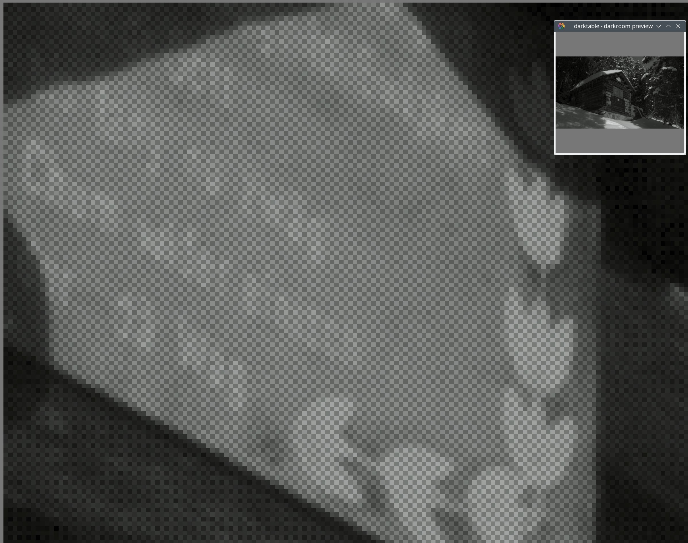
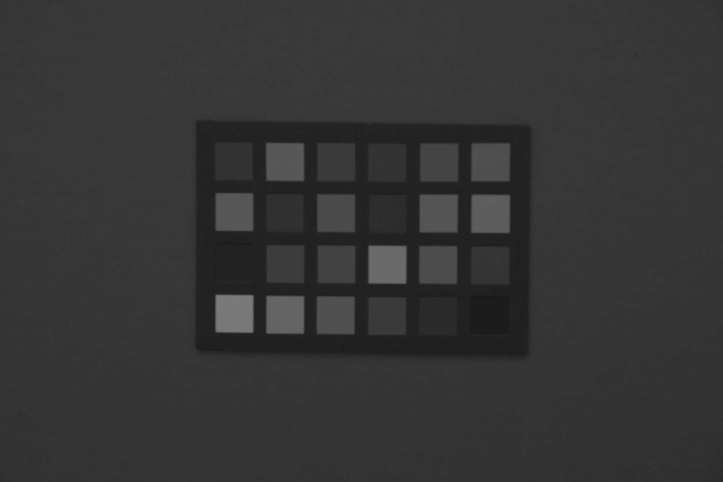
Raw sensor data. Each pixel represents only how much light was captured, but not the colour. This is what the sensor recorded.
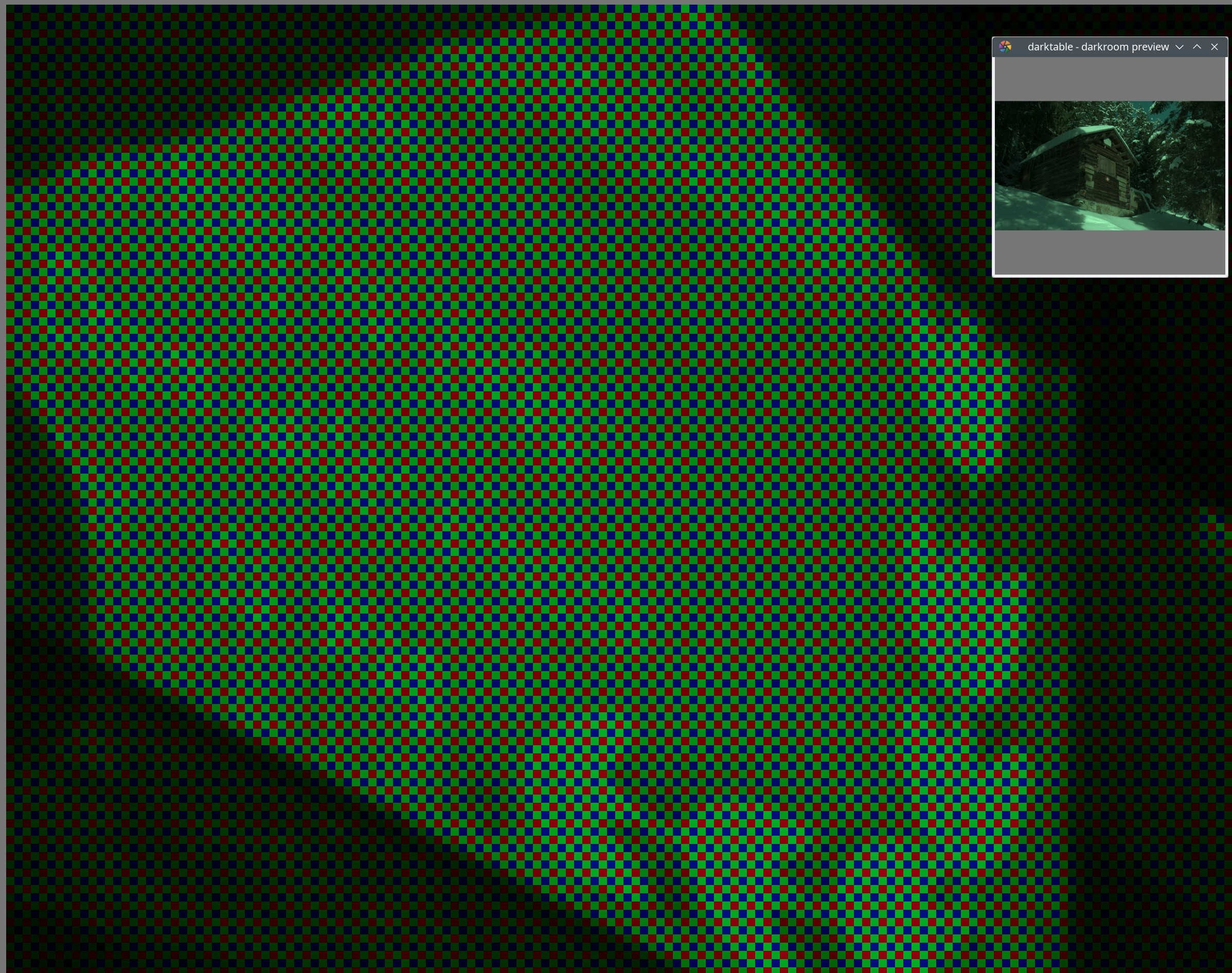
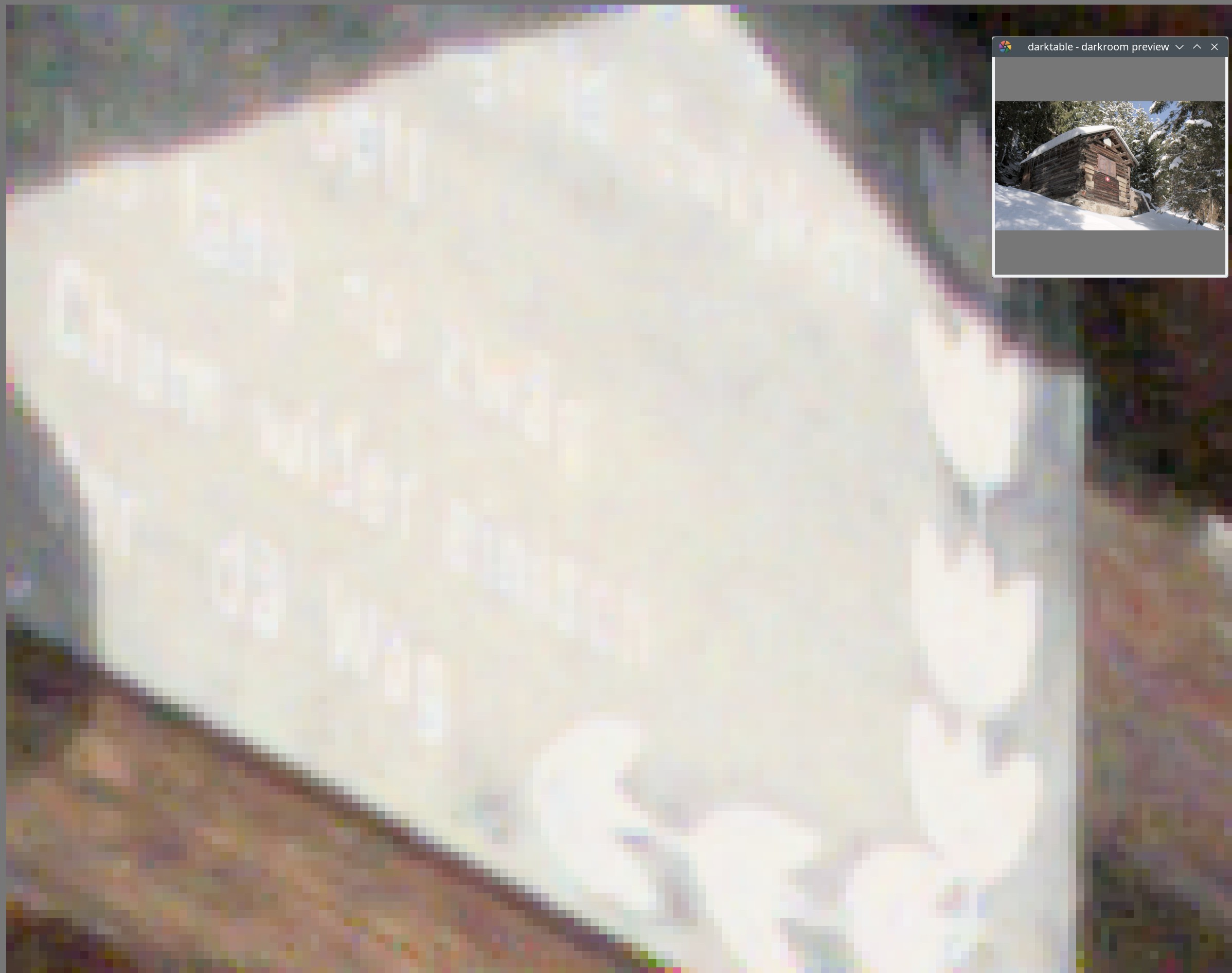
All pixels marked with red, green or blue, according to the Bayer pattern (odd lines have alternating green - red - green - red filter in front of the pixels, even lines have blue - green - blue - green). Note the strong green tint; this is characteristic of raw images: for the Bayer sensor, half of the pixels are green, only 1 quarter is red, and 1 quarter is blue, and we have not applied the white balance multipliers, yet.
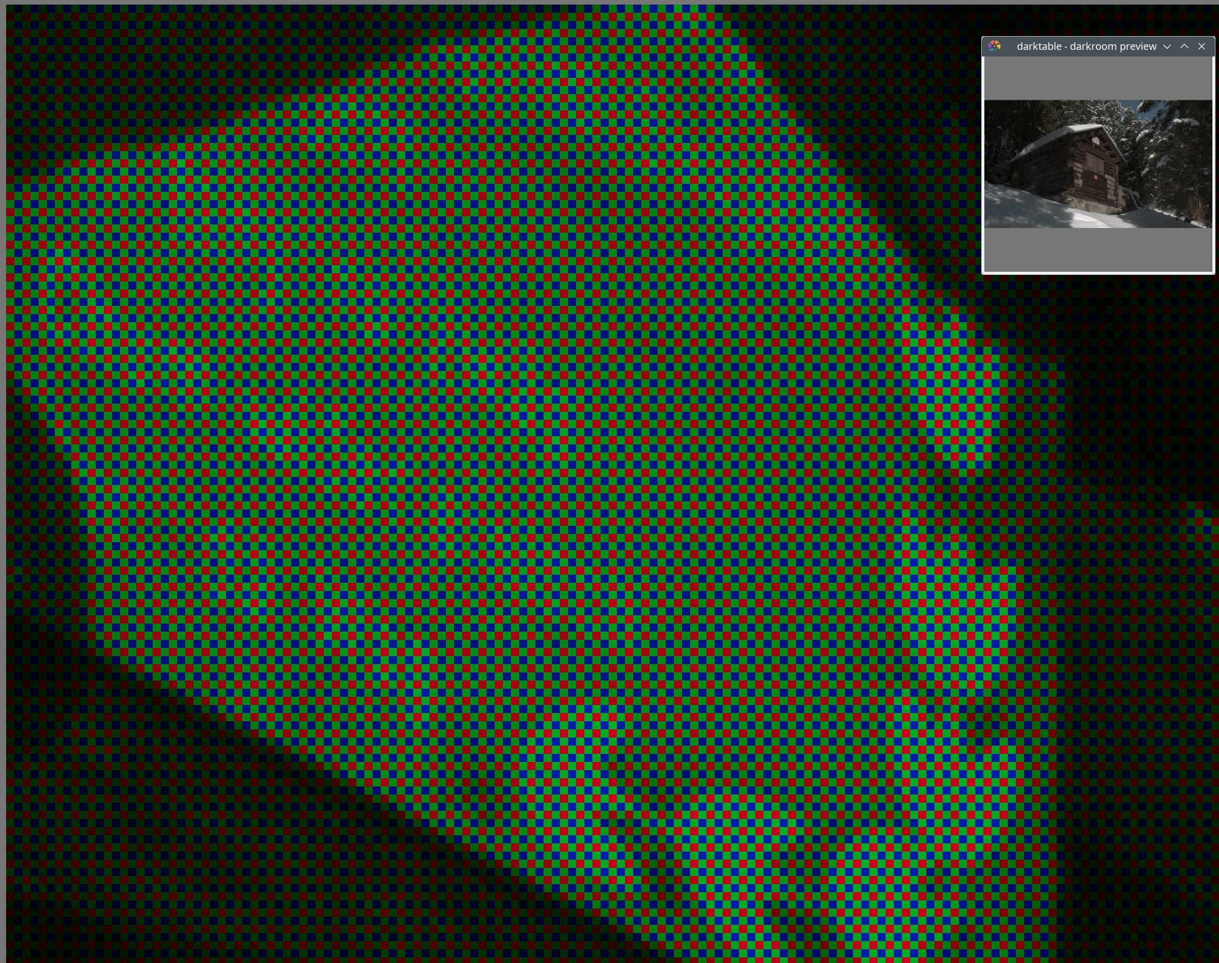
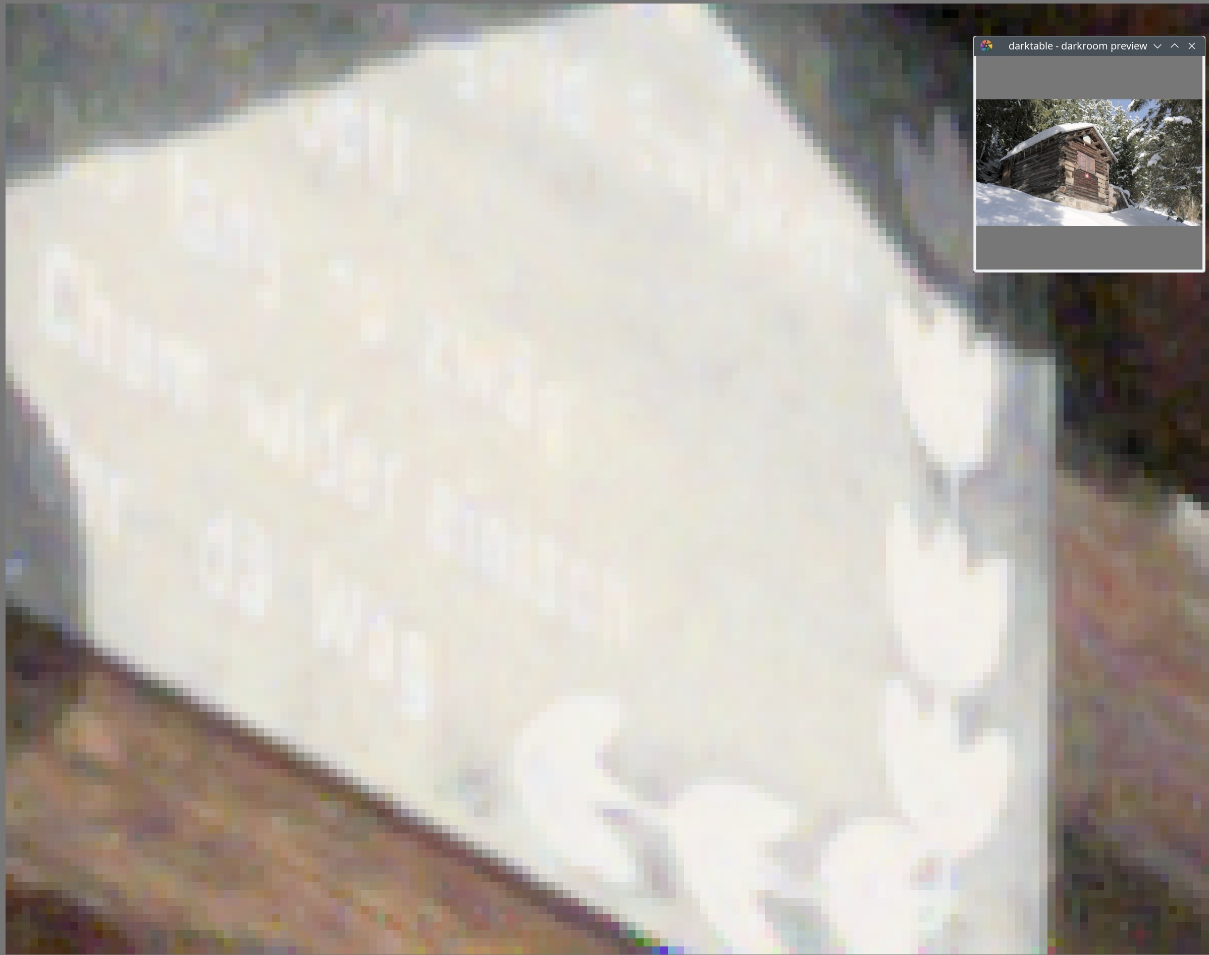
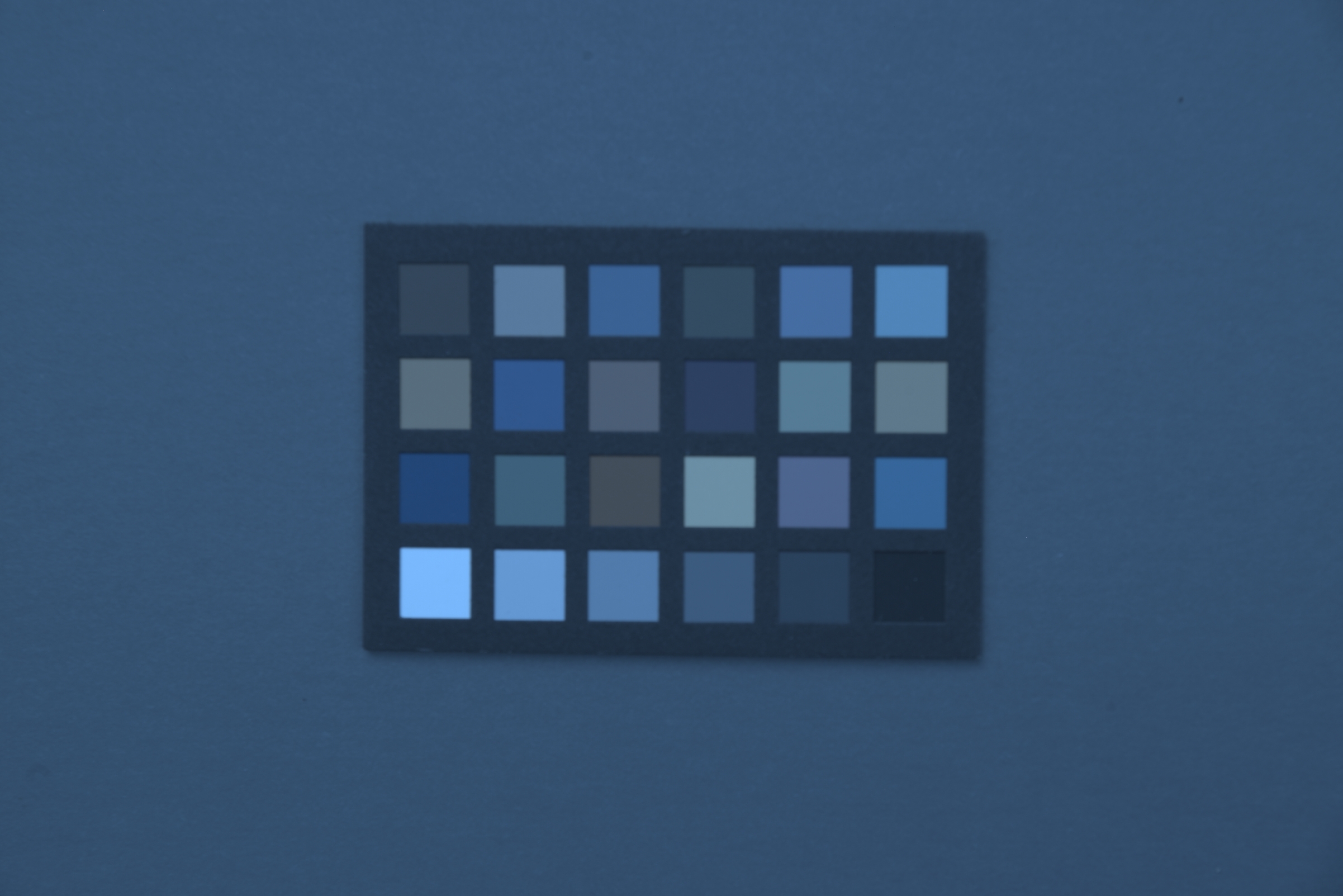
The camera records white balance as multipliers: how much red, green and blue values have to be boosted. Here, those brightness adjustments have been applied. Note that the small preview image now looks much better, the green cast is reduced (at least on the snow), but still present (check the sky).
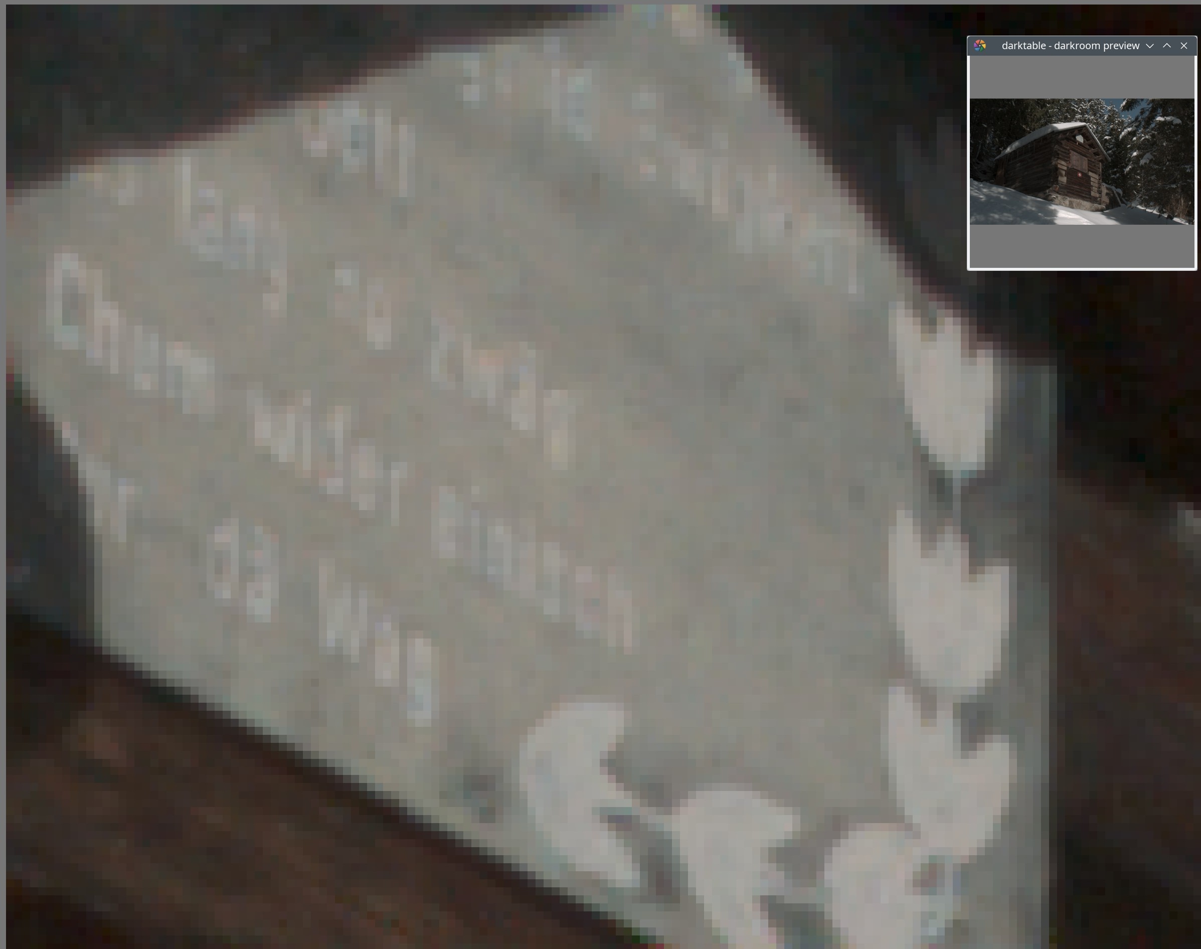
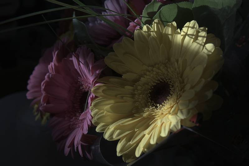
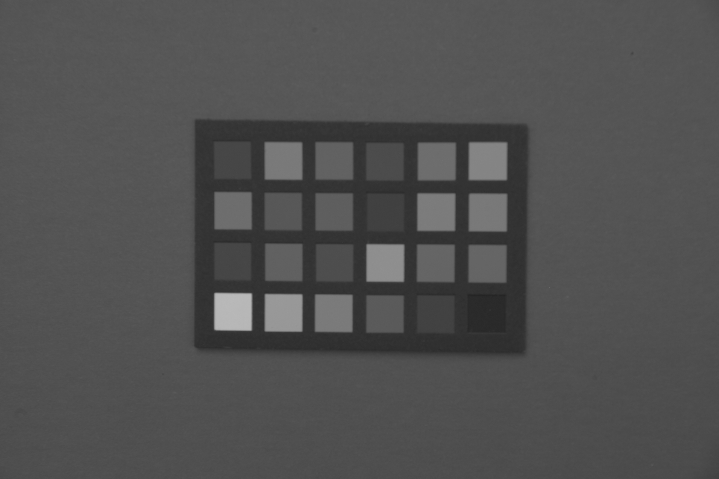
The image has been demosaicked. For each pixel, missing colour information was estimated based on the nearby pixels. Since now we have red, green and blue equally represented, the green colour cast is gone.
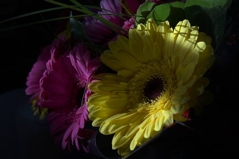
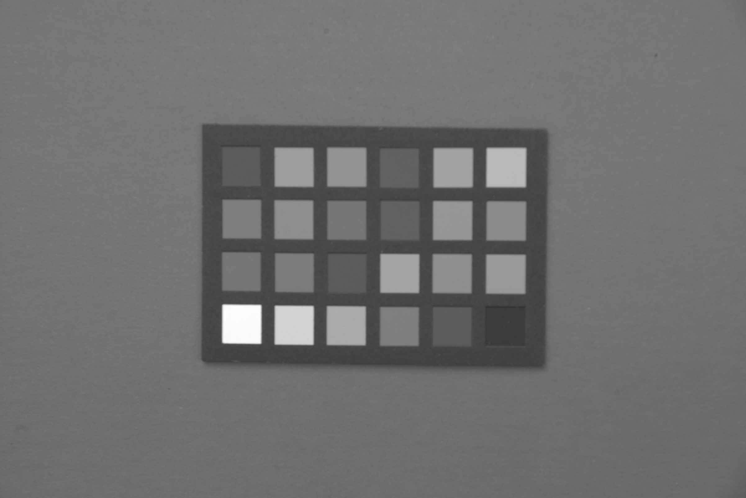
The camera’s specific colour profile (its own red, green and blue primaries, replacing the previously used generic ones) have been applied. The change is not that easy to see, but without this step, colours would be slightly off.
A bit more about that transform. It’s two things: 1) color gamut transform, and 2) a non-linear tone curve. In order to turn off the export transform and keep the tonality, I had to add a gamma curve to replace the one in the export color profile.
To turn off the color part, I at first removed the output profile from the associated property. It still transformed, scratched my head for a bit, then remembered I made it default to sRGB if nothing was specified. I also then recalled I had an output property called ‘excludeicc’…
Knowledgeable readers will note that the large off-diagonal coefficients, especially for green, do not bode well for noise performance, let alone the big diagonal multipliers for green and blue!
Here are the raw layers extracted by a non-FOSS app:
Please forgive my complete lack of, probably basic, knowledge:
In the demosiac portion of the darktable manual (v4.6), it mentions that there are options for “threshold” (PPG),“refinement” (LMMSE) and “color smoothing”. Do these adjustments change how missing color information is estimated? Or is it earlier/later in the pipeline you described…or not even related?
The process of demosaicing is a interpolation to reconstruct the full color image and so the parameters of each model just impact the nature of that interpolation math used at the time of demosaicing ie impacting the output from the module at that point in the pipeline as far as I undertand that and how it relates to what you are asking…
They are colour estimators. You can search for them online by name, if you want to figure out how they work. If you can read code, the source code is on GitHub.
A very simplistic visual of the process can be viewed on pages 129-131 here… of course each model provided in DT and RT or any other raw editor are more complex ways to do the reconstruction than shown here… this is a great set of slides covering a lot of the basics of digital image capturing and processing… you might find it interesting or bits of it anyway…
A bit offtopic but a few days ago I was reading about Kodak and Bryce Bayer and it’s impressive how he came up with the Bayer pattern in only a few months (if not weeks) and it’s still the default pattern today, used almost everywhere. The intuition these top tier scientists have is always impressive and fascinating, a modern example is the 10x or 100x programmers like Fabrice Bellard or similar.