How can I configure darktable to get the RAW RGB values.
Both in the UI and the code? (Ideally the code)
A little bit of background I have started hacking the negadoctor code with initial goal to make the predicates from the algorithm derived from Kodak Cineon system, better aligned with UI.
A have a number of goals, but one simple one was to change the colorpicker to display density values.
I got the code working until I released the the sensor values were not linear, or at least not as I expected them.
To keep things simple I will attach a simple raw file of a step wedge along with the xmp file. Every two steps should be a density change of .3 or 1 stop. (You can create the comparison tiff file using the dcraw command) i.e. step #3 should transmit half the light as step 1.
If I use dcraw -v -w -4 -o 0 -T DSC_7373.NEF I get values that I expect.
In darktable I get much brighter (larger) values both in the UI, and internally in the code when I take values from the pixel pipe represented by dt_aligned_pixel_t.
I have changed the input colorspace to linearRec2020. I have manual adjusted the rgb sensor gain using the whitebalance, hopefully that can be seen with the xmp file.
rawproc, my hack raw processor will give you raw values. Open the file, select no for default processing, and read away. Now, the readout from the mouse hover is0.0-1.0 float, but you can multiply those values by 65536 to get the integer values.
I was using the values that come out of the pixel pipe contained in dt_aligned_pixel_t in what I am guessing is a callback method called process()
I wonder is this because the internal representation is Lab? Just guessing since I move my hacked version of negadoctor to just after the demosaic module I get values much closer to what I was expecting.
My Modified version of the colorpicker still gets the wrong values, but perhaps I can solve that another way.
Ultimately my goal is hack the negadoctor module, which I have started on.
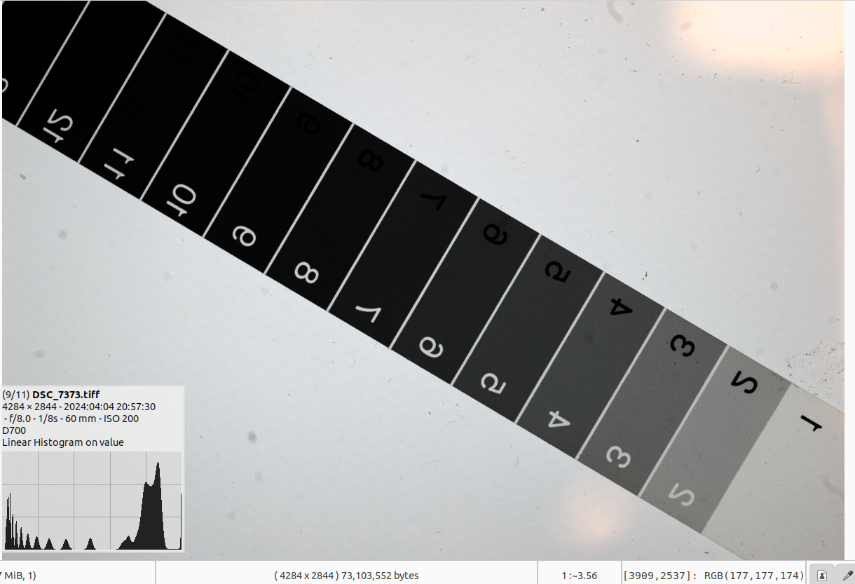
Yes, thats a clue. If you open the tiff however with another editor, and without any input profile and read the raw values in the tiff you will get the values that I expected, and you can correctly calculate the Density values. i.e. step 3 is .3 greater than step 1.
For example in the tiff, of which I will attach to screenshots. I get RGB values of around 170/255, and for step 3 I get values of 90/255. i.e. nearly half. This is what I expected from my d700 in raw.
I don’t get this in DT.
Perhaps I have an incorrect understanding of how the camera works.
I figured it out! I will try and summarise, perhaps others may find it useful.
a. The values in the pixel pipe are usually linear, and if they come directly from *.NEF file or similar, they will stay linear, until somewhere towards the end.
b. If you use an input color profile that is linear such as the camera matrix or linearRec2020 it will stay linear until somewhere towards the end.
c. If you use an input color profile such as sRGB that is non linear (has gamma != 1) with your linear camera data (*.NEF etc) then it will be non linear internally until the end. If the gamma of you input profile matches the gamma of your display profile.
So for option C the value available to the color picker will actually be linear! and match the output of dcraw -v -w -4 -o 0 -T *.NEF
For option a and b the linear data is changed as some point to non linear for display, the new values reflect the gamma in the display profile.
The colorpicker looks at values after the display profile AFAIK.