G'MIC exercises

Really cool! It’s probably not obvious to many what purpose minimally spaced noise has, but it’s not something you would use directly - it’s something you can build things with. It becomes trivially easy to make certain patterns:

noise_circles

And also has uses for anti-aliasing and such like. Even the cones of the human eye have a pattern based on the same principal!

Your example looks like what the “Stencil” G’MIC filter produces:

It does look like that, yes! However, I was thinking of more complex interlocking ‘blobs’ a bit like what the image from earlier was suggesting:

image

This would only be one such ‘blob’. I think that it would depend on whether we could have multiple travelling salesmen on a single image without their tracks overlapping. Segmentation then noise, travelling salesman and then fill for each segment.

@David_Tschumperle Looking at @garagecoder dots-in-a-ring image reminds me of the autostereogram, which I think would be a fun filter to write and use. :wink:

@afre, I had a look this morning about the problem of including .gmic files from user.gmic, on Windows.
Here, I don’t have any problem to be honest. What I’ve done is :

  1. Put the following in my file %APPDATA/user.gmic:
cli_start : 
  l[] m ${APPDATA}/custom.gmic onfail endl
  1. Create a new file %APPDATA/custom.gmic whose content looks like this:
my_com : 
  sp lena mirror c b 5
  1. Now, from the command line, I can type:
$ gmic.exe my_com

and it indeed displays the modified lena image. I’ve tested both with the MSYS command line (bash), and the original (shitty) DOS-like console (see screenshot below).

If you look at the screenshot carefully, you’ll be able to see the log message emitted by the command cli_start defined in my user.gmic. Add embracing v - and v + to cli_start to hide them.

So now, what can I do to help ?

1 Like

Thanks. Looks different from what I tried. I will look into it when I am less tired.

Update: it works!

BTW, what does l[] mean? I recall asking about e versus e[] before… is this related to that?


I have been struggling to figure out a good way to thin, centre and refine edges (of the gradient norm result). E.g., when I do

gmic sample tiger gradient_norm

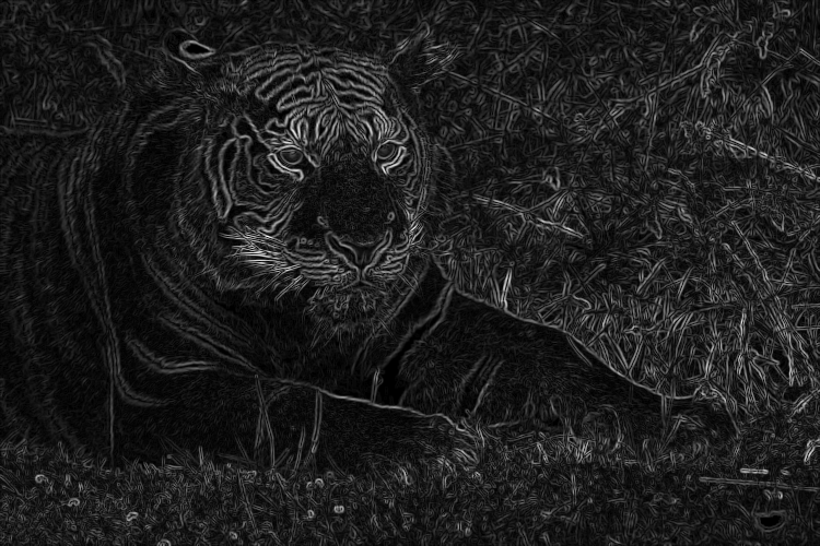
I believe there are two things going on (correct me if I am wrong):

1. Brighter where there are edges.
2. Wider where edges are sharper.

is possible Diffusion curve with gmic?


1 Like

Filter Solidify ?

1 Like

thanks!

Gradient Norm


My attempt to make the lines more balanced in brightness and thickness.


Remarks

I would like the lines to be more even and defined, sort of what you get from colouring book outlines; actually that might be a good filter to work on (or maybe something like that already exists…).

At the moment, there are inherent weaknesses to the gradient norm method. The two I mentioned before: uneven brightness and thickness. And a few others: thin objects such as the whiskers “double”, and tips and corners either disappear (darkened) or become less defined (rounded).

Also, if you toggle between the original sample tiger and my results, you would see that the outline is not smack dab in the middle of the edge. It ends up either on the bright side or the dark.

If you want edges to be balanced in brightness and thickness, Canny edge detection does that directly. Eg with ImageMagick:

magick tiger.png -canny 0x4+10%+30% tiger_canny.png


This has lost very fine detail, eg the whiskers. You could do multiple Cannys and combine the results.

I can’t find Canny in the G’MIC docs. Perhaps it isn’t available.

@Stampede asked about Mixer [PCA] and I gave an uninformed answer.

I know people who frequent this thread can do better than that. :slight_smile: Additional thoughts:

1. I was curious what the command would be in CLI and so output the command to the layer name. :thinking: The command is kind of lengthy; are those values for the gradients?

[G'MIC] Mixer [PCA]: fx_mix_pca 0,0,0,-1.5,0,0,-1.5,0,0,0,3,248,98,2325.2000000000003,111.79512900164166,114.29732606890039,67.953656912764956,2315.6918711327867,1198.1961603337977,1119.5840052975143,1198.1961603337977,1460.9525680609997,972.14804576863651,1119.5840052975143,972.14804576863651,1028.2088564317926,0,50,50

If so, they don’t require user input at all. Should they belong to the argument list?

2. It would be great if we could get a rgb2pca and pca2rgb, though I don’t know if that is meaningful or useful. If anything, it would be an educational demonstration on how to get to and back from 3 PCA components.

3. I guess the input for PCA manipulation isn’t limited to RGB. It could be any number of channels, right? Does the number of input channels correspond to the number of PCA components we get? Or could we decompose the input image to any number of components, sort of like split_details?

Apologies for asking so many questions, especially when many of you are busy people. I hope I don’t tempt you away from your important work. :stuck_out_tongue:

@afre , if you have ImageJ on your computer, you can try the 3D Color Inspector/Color Histogram plugin for ImageJ.Here is some help for the plugin, but the help was written, before the PCA functionality was added (see second hyperlink).

With this plugin for imageJ, you can make the color distribution within different 3D-color-spaces visible. With this tool, maybe it is more easy to understand whats going on.

The nice thing of the G’MIC “Mixer [PCA]” filter is that you also can shift and rotate (the color distribution) in 3 directions. That isn’t possible with the imageJ plugin.

This G’MIC mixer is useful in images that have a narrow color distribution, like faded images or images with color cast. With help from the PCA you now have the right directions within the color distribution to work with. So now, I don’t have to think about RGB or AB, that’s extreme helpful for lazy people like me :smile:. In this PCA directions now you can shift in case of color cast (second slider) and widen the color distribution (first slider) to have more color-contrast between the opposites of the PCA direction. With the third slider you can rotate the color distribution around one of the PCA “axes”. The other two PCA opposites will rotate, not the colors on the axis. Therefore it seems a little bit strange, but with this in mind, it is more easy to work with.

You can also use this mixer to make the color distribution smaller (with first slider). Then there will be less color contrast within the PCA axis . You can also shift with second slider to color grade your image.

I hope this information is useful. If it is wrong on some places, other people here can correct my information. :wink:

2 Likes

I wish to do a distortion of the degrade from the difference of two image

I think that using the difference between source_gseg and target_gseg can distortion source_gpos and obtain target_gpos

2 Likes

I think that it can paint with colours the “morph layers” distorsion

A version to reverse of this:
https://www.imagemagick.org/Usage/mapping/#distortion_unified

1 Like

@garagecoder, just to thank you again for your wonderful noise_poissondisk command. That’s my new favorite weapon in my arsenal. I use it all the time, it’s so convenient to get a random spatial sampling uniformly distributed like this ! :beer:

1 Like

I’ll try my hand at making a Cubehelix filter after probing Color.js’s README on GH for stuff about colour spaces. It’s not quite as easy as splitting channels and binding them to sine waves.

Interesting, you might want to start with the matlab code - it probably needs very little modification for the gmic math parser.

1. What is the best way to input all of the sample images? My lazy way is

gmic repeat 100 sp done remove_duplicates

2. animate messes up the aspect ratio of images. How can I prevent that? E.g., if I do

gmic repeat 100 sp done remove_duplicates animate 2000

I was thinking of a different method entirely which involves splitting the channels but this might work. The Matlab code does seem a little tricky for me to understand though. I can sort out the if and for stuff just fine but I’m unfamiliar with matrices in G’MIC. map looks like it’s initially a two-dimensional matrix of zeros and I have no idea how it works. The stuff in the if structure is also difficult for me to understand. I also have no idea how vectorN works.

Mind you, I’ve found an extension of Cubehelix which allows for interpolation between any two different colours. It’s quickly becoming something that I don’t think that I can do because of how much technical stuff it requires.