Why not using the regular commands rgb2ycbcr and ycbcr2rgb ? The RGB<->YCbCr transformation keeps the [0,255] value range of the image values, by nature.
I was thinking of it being similar to what HSV8 is to HSV. I’m still not sure what the differences are. rgb2ycbcr isn’t quite cubic, too, it’s closer to a rotated cuboid thing. Seems like a matrix transform more than anything else.
The HSV8, Lab8, and other similar color space names are used when the usual transformation does not produce values in range [0,255].
But for YCbCr, fortunately, it does originally, so no needs for YCbCr8
It would be nice if the YCbCr conversions had the option to follow various recommendations; e.g., Rec. 601 (which it is currently), Rec. 709 and Rec. 2020 / Rec. 2100.
Here’s the latest poisson disk noise in this commit - I’ve tried to keep it readable!
Main differences from the algorithm it’s based on:
It uses a sorted “kernel” of relative positions for the proximity search (meaning grid cells closer to a potential sample are searched first).
The grid uses 0 to indicate an empty cell (not -1), reason being we get a “free” boundary check from G’MIC.
I’m hoping you can take this and give it your usual sparkle
The kernel could even have some cells removed based on distance (less cells to search for every sample - big speed gain probably), but the maths is starting to make my brain turn inside out so I’m leaving it as is.
Edit: thought it interesting to note some speedup attempts which didn’t help much:
Direct sampling from the annulus instead of random rejection
Using a fixed size samples buffer instead of dar_insert - this proves
your dar functions are really great! Practically no performance penalty but less ram used.
Wonderful @garagecoder !
I took your command, modified only it a little bit , and added it as a new command noise_poissondisk in the stdlib.
What I changed basically is I removed the value parameter to stay coherent with the behavior of the noise command (in salt&pepper mode), which was the most similar effect in G’MIC so far.
So the value used is always the maximum value of the input image, or {iM+1} is the image is constant (just like noise does). I don’t think this is a big deal, as I guess this type of noise will be mostly used on zero-valued images.
You have done a really cool contribution here (again!), thanks a lot !
EDIT : The good properties of the noise distribution is clearly visible when we inject the generated noise points in the tsp command, to solve the Travelling salesman problem. Look at that nice random but regular texture !
Really cool! It’s probably not obvious to many what purpose minimally spaced noise has, but it’s not something you would use directly - it’s something you can build things with. It becomes trivially easy to make certain patterns:
And also has uses for anti-aliasing and such like. Even the cones of the human eye have a pattern based on the same principal!
It does look like that, yes! However, I was thinking of more complex interlocking ‘blobs’ a bit like what the image from earlier was suggesting:
This would only be one such ‘blob’. I think that it would depend on whether we could have multiple travelling salesmen on a single image without their tracks overlapping. Segmentation then noise, travelling salesman and then fill for each segment.
@afre, I had a look this morning about the problem of including .gmic files from user.gmic, on Windows.
Here, I don’t have any problem to be honest. What I’ve done is :
Put the following in my file %APPDATA/user.gmic:
cli_start :
  l[] m ${APPDATA}/custom.gmic onfail endl
Create a new file %APPDATA/custom.gmic whose content looks like this:
my_com :
  sp lena mirror c b 5
Now, from the command line, I can type:
$ gmic.exe my_com
and it indeed displays the modified lena image. I’ve tested both with the MSYS command line (bash), and the original (shitty) DOS-like console (see screenshot below).
If you look at the screenshot carefully, you’ll be able to see the log message emitted by the command cli_start defined in my user.gmic. Add embracing v - and v + to cli_start to hide them.
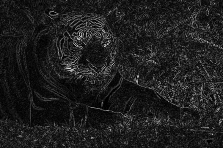
I would like the lines to be more even and defined, sort of what you get from colouring book outlines; actually that might be a good filter to work on (or maybe something like that already exists…).
At the moment, there are inherent weaknesses to the gradient norm method. The two I mentioned before: uneven brightness and thickness. And a few others: thin objects such as the whiskers “double”, and tips and corners either disappear (darkened) or become less defined (rounded).
Also, if you toggle between the original sample tiger and my results, you would see that the outline is not smack dab in the middle of the edge. It ends up either on the bright side or the dark.