input device transforms and out-of-gamut blue

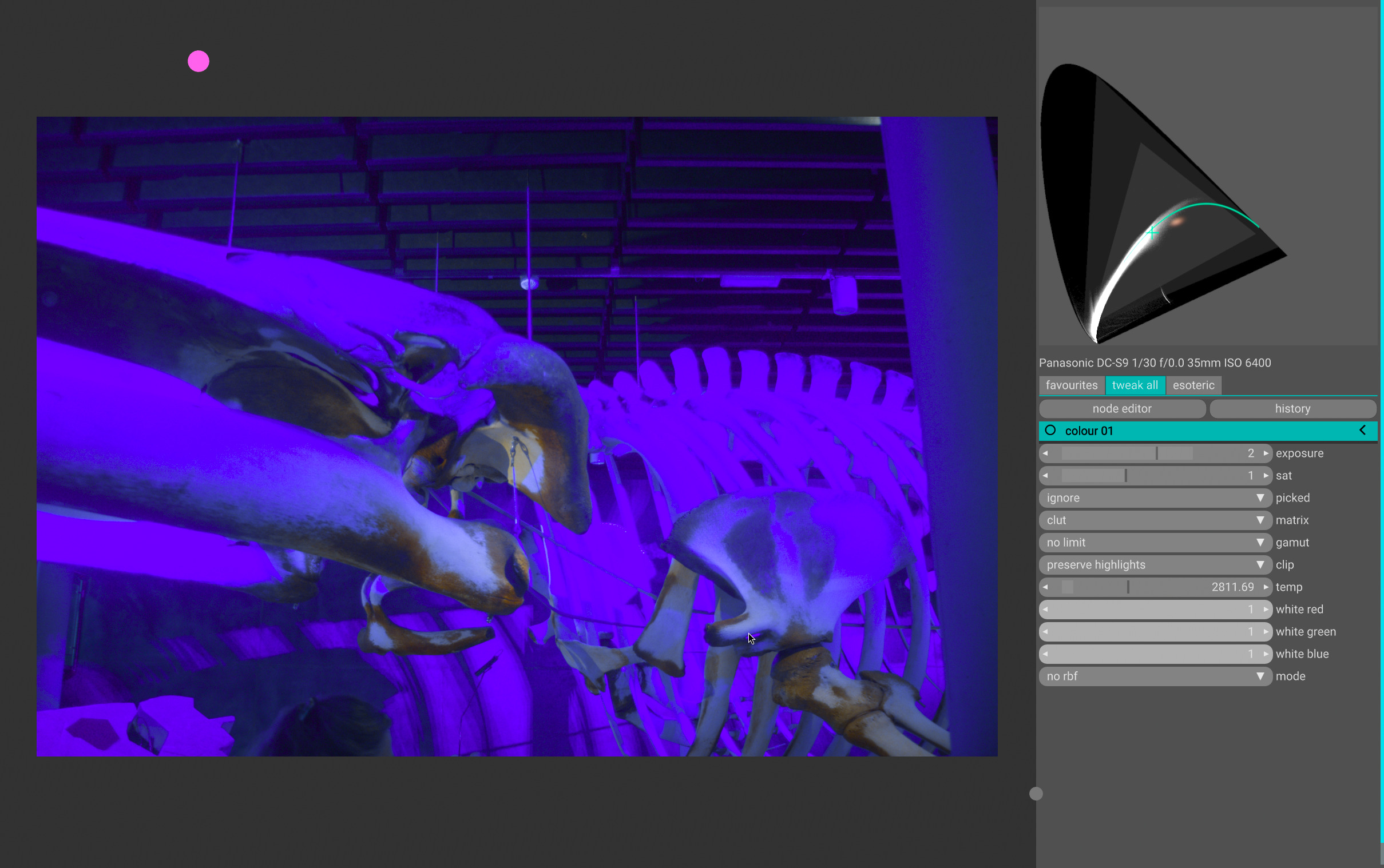
i noticed we don’t have a nice post with images to point people to about this problem (see title). since recently @Billal asked about it again, i thought maybe an illustration helps. consider this picture i recently took in a museum:
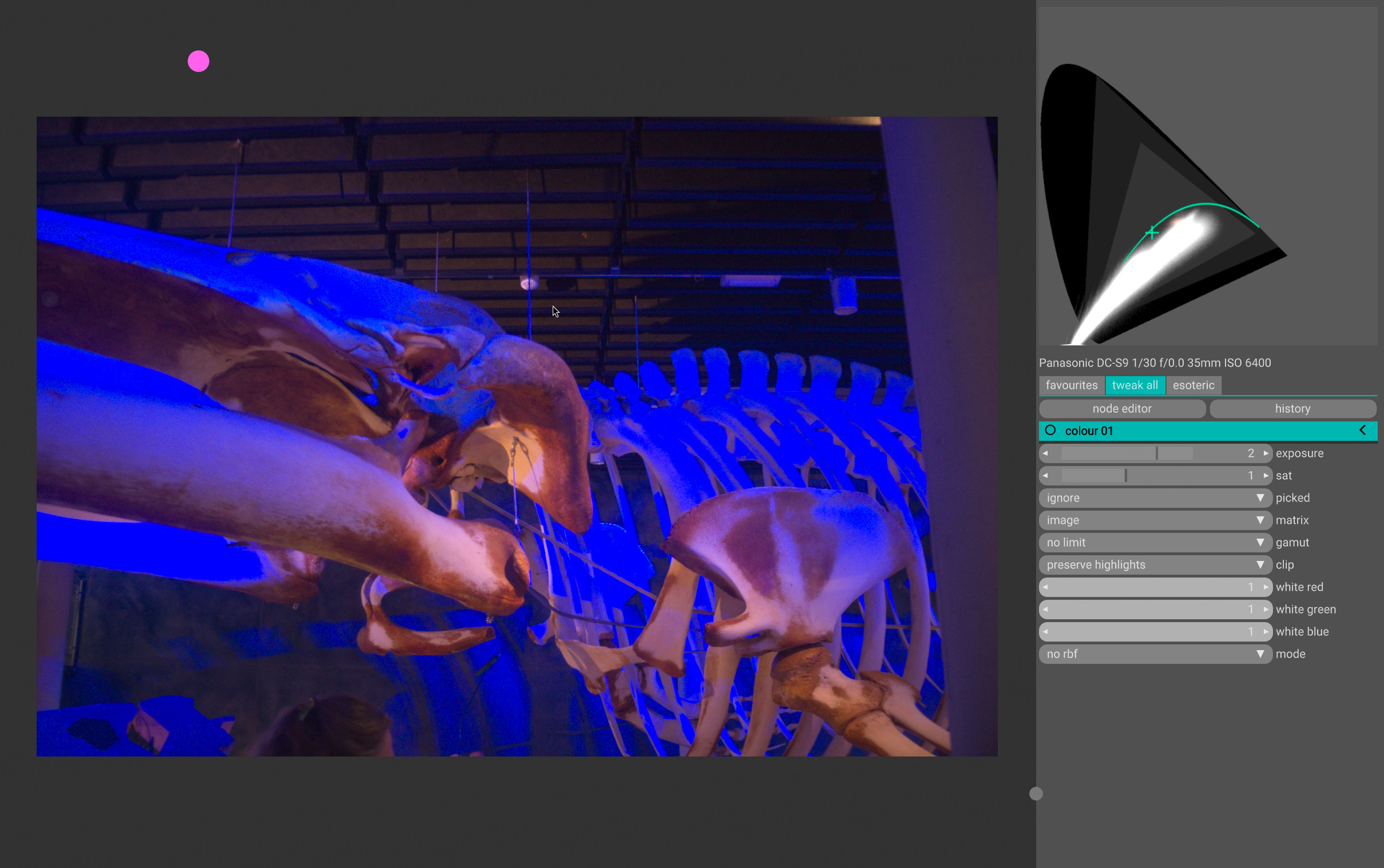
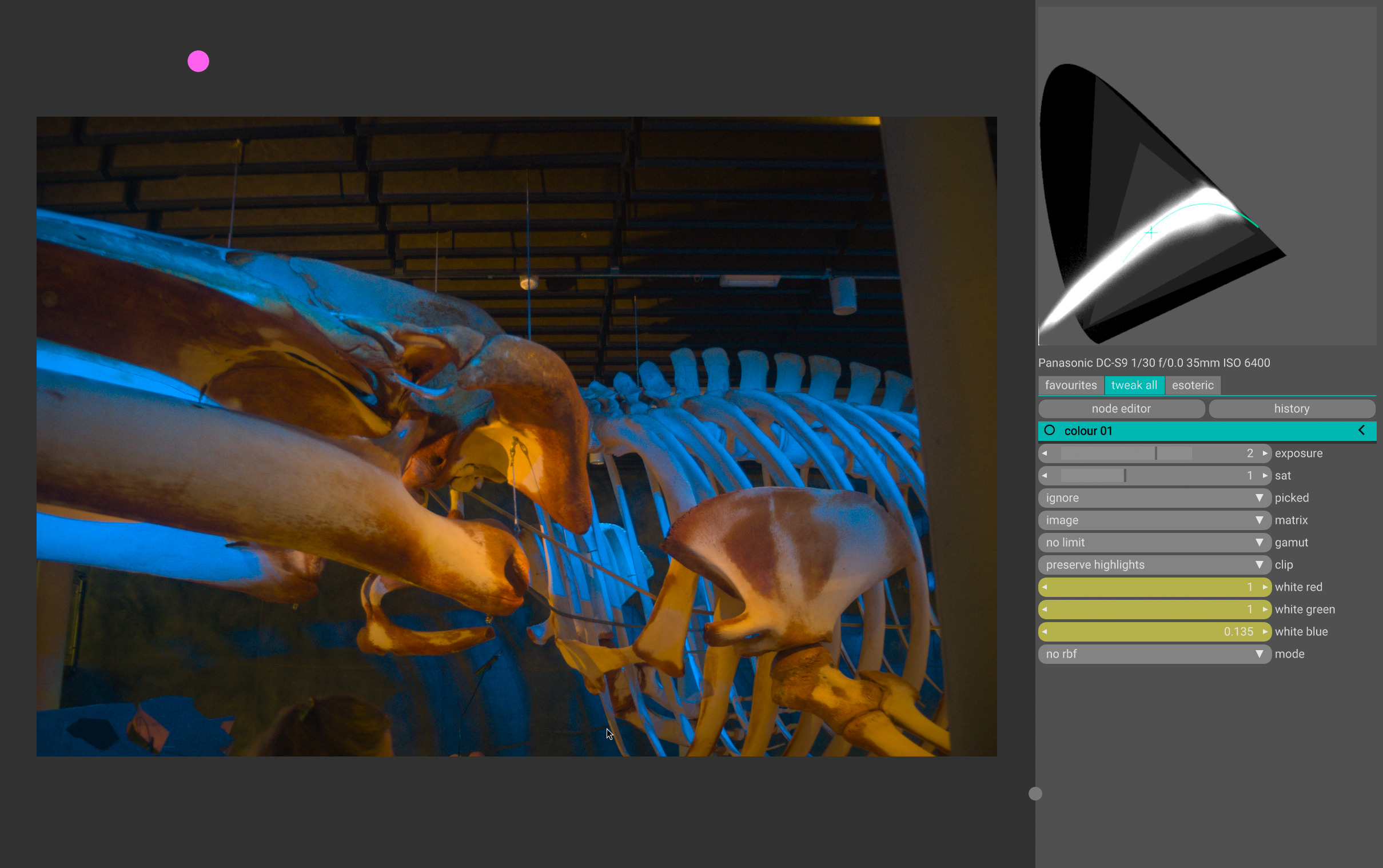
it has severly blue lighting. the matrix is optimised for, uhm, maybe skin? cc24? certainly not for these extremes. you can see in the cie chart (top right), that those clipped blues are way beyond reason. of course messing with white balance (CAT16 here) doesn’t help:
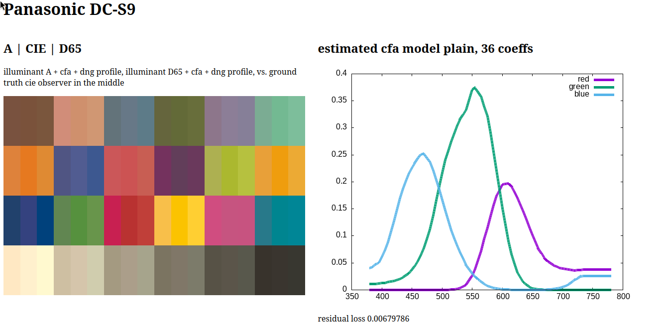
i don’t have spectral measurements of this camera’s spectral sensitivity fuction, so i used vkdt mkssf to create one (using default parameters):
with that, you can create dcp profiles as @ggbutcher does. i created a look-up-table-based input device transform using vkdt mkclut:
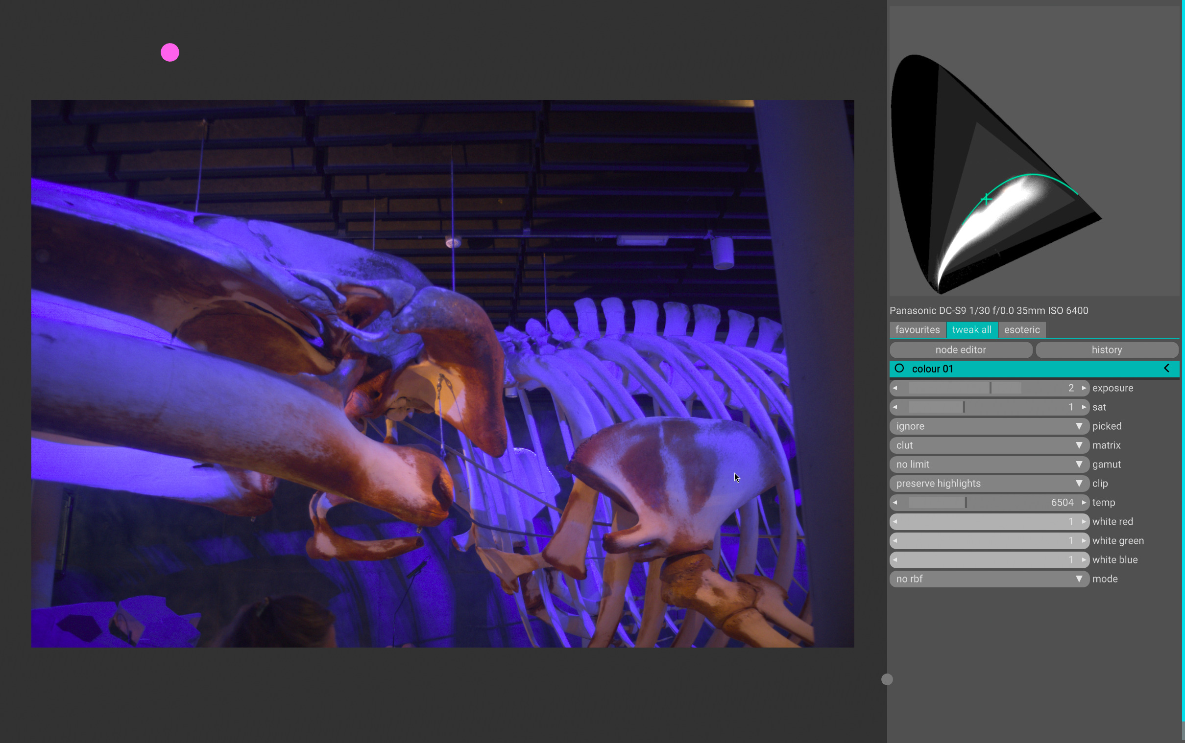
and as you can see it keeps the starting points nicely within the spectral locus.

@niklasiivari recently vamped this code up to support a wider range of temperature interpolation, so you can now move relatively freely with the white balancing in this realm (staying within spectral locus):
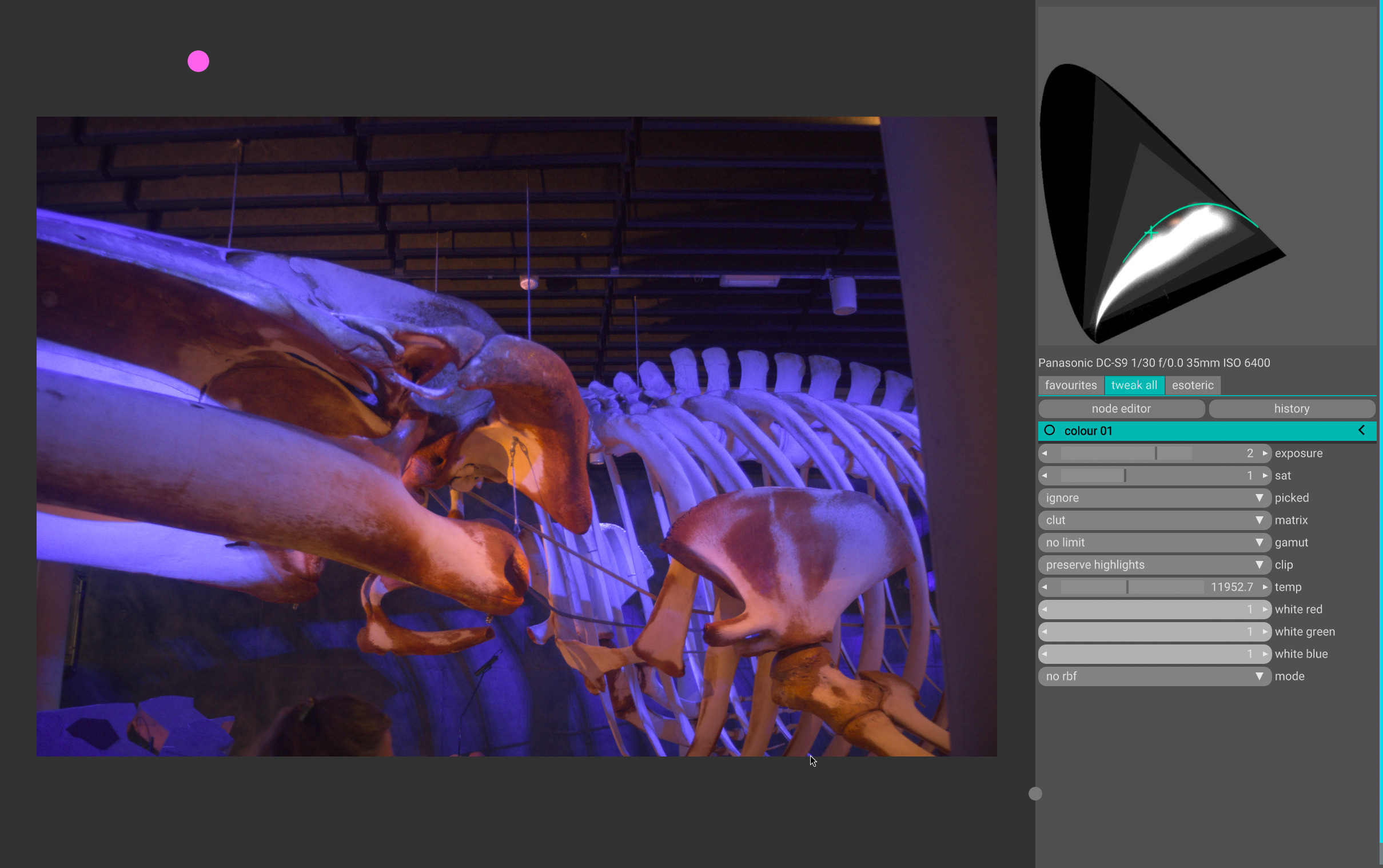
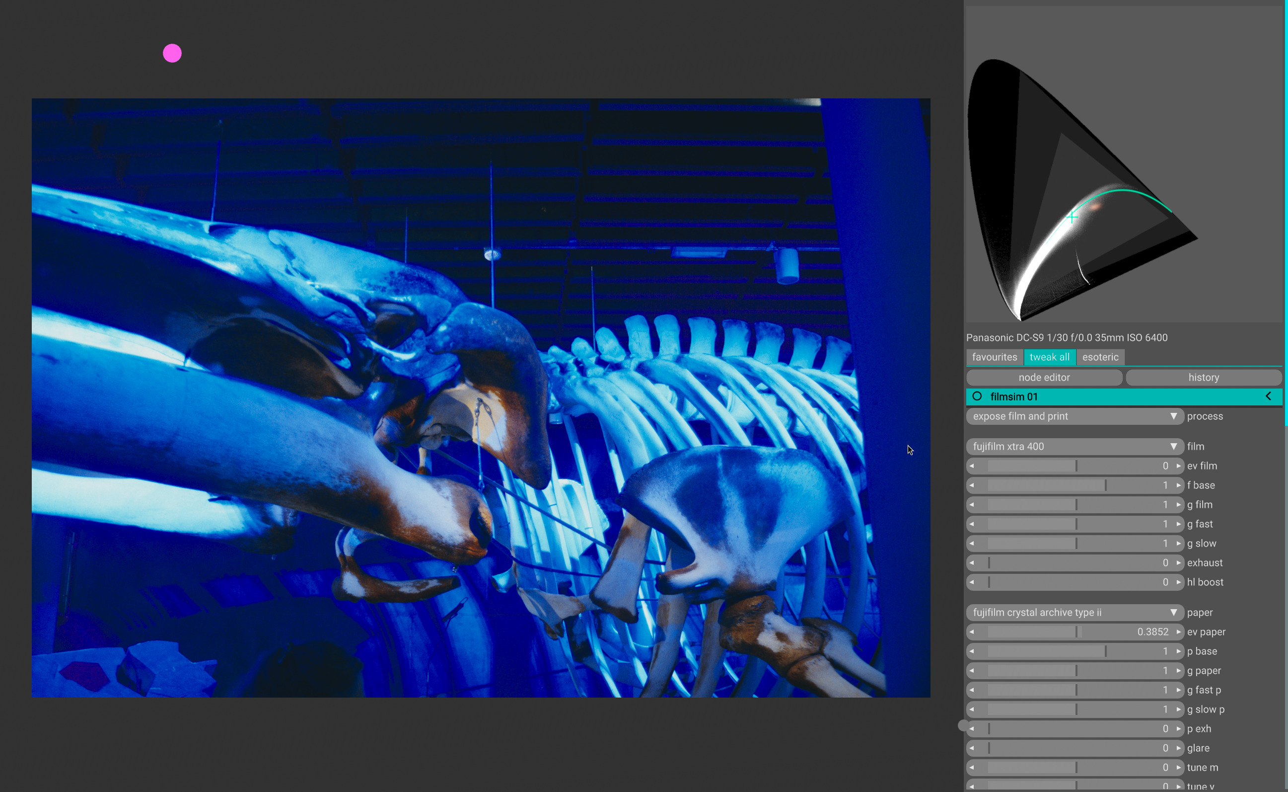
…and then edit to taste, for instance add spektrafilm sim on top, now with reasonable starting point. note that this module contains now also a few spectral white balancing extra controls (because once we’re in spectral we might as well do things right):
hope that illustrates it well!

btw: while for spektrafilm/upsampling being inside spectral locus is enough, sometimes you’d want to limit your output to within rec2020 or even rec709. that’s possible with the gamut.pst, though i find it desaturates this particular image a bit much:

btw2: this is camera rgb (re-interpreting values as bt2020, you can tell they are inside the larger triangle in the cie diagram). while numerically well-behaved, the colour rendition is of course wrong:
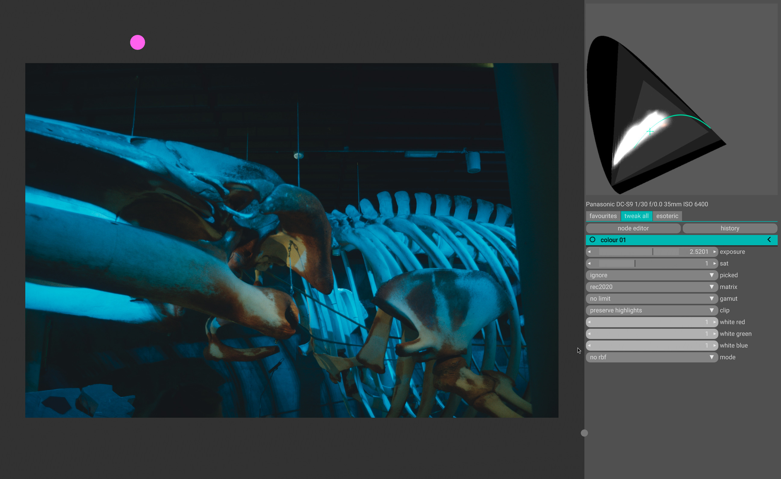
btw3: i took screenshots of my 10bpc pq framebuffer here and tbh i don’t know what that does to the colours. looks about right on my screen, and you’ll get the idea following along the cie chart.

12 Likes

Could you please share the raw?

yes.

Panasonic DC-S9.lut (12.0 MB)
P1001244.RW2.cfg (5.9 KB)
P1001244.RW2 (22.7 MB)
consider this licensed CC NC SA.

2 Likes

heh yeah i believe troy would like to wire these images straight to our brain/cognition, preferably without human visual system in between. short of that i’m happy with values that don’t imply negative energies for now :slight_smile:. even if it means a bit of guesswork (guessing device ssf and likely spectral shapes of the stimuli reaching the lens).

also i’d recommend against bypassing the input transform (as seems to be hinted at as solution in the mastodon thread). that is essentially giving up and leaving colours completely to manual guesswork.

1 Like

I agree that this is a good enough solution for now.

About the use of the native rgb records, I used this approach quite extensively but as you mentioned it’s pretty difficult to manage. A friend of mine recently changed my perspective in this regard, where he said even though that the native records are a well behaving tristimilus in the context gamut limits, they’re not a set of values meant to be viewed ala log encoding. So, a transform is a must.

What you did here is quite similar to my approach with dcamprof profile making, they have an option for a “lighter” matrix that takes care of the vector rotations and little to no push.

Also, you can try to bypass the observer space by attempting to match a digital SSFs to film’s and see for yourself. (I think this is intresting), but you’ll fall again to some metameric failures trying this.

As for Troy, he might seem to complicate things and he does sometimes (sorry peep), but what he tries to communicate is simply the breakages that these transform introduce to our images on a cognitive level and how important for us to understand the spatial components of pictures and how film have a clear advantage when compared to digital. So to put simply, negative values are not just some random numbers that we can map them back to our display limits, they’re causing a spatial and cognitive breakage when we’re observing the pictures and no gamut mapping will solve this.

Also, any transform that we make must be stress tested, and what I mean here is not just high sat neon lights etc. But they should be put to the test with a clear goal, which is they do not cause breakage to the additivity domain and gradients which we’re extremely sensitive to (transparent materials, reflections etc.). Even though the values can exist within our container it doesn’t mean they’re safe.

Btw, what you guys did with the bandpass and surface adaptations is absolutely amazing, I thought about it for a long time now.