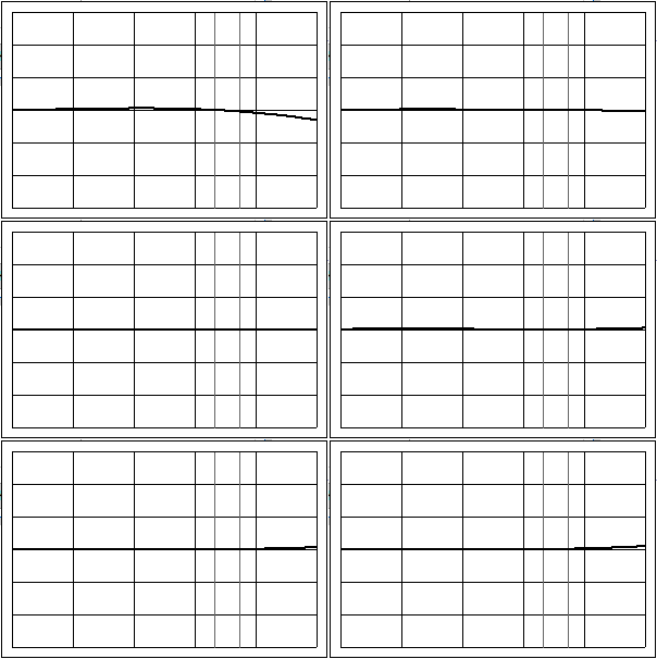
So, I’ve read a few tutorials on how to profile your lens to obtain distortion correction parameters for lensfun. Following a combination of these approaches ([1], [2], [3] and [4]), I got reasonable results. However, the values for a, b and c that I got have me puzzled (table below is WIP using Hugin following Wilson Bronger’s method):
Tamron SP 70-200mm f/2.8 Di VC USD G2 (A025)
distortion(70mm)  =  0.00184, -0.01278,  0.00975
distortion(80mm)  =
distortion(90mm)  = -0.00071,  0.00153, -0.00562
distortion(100mm) = -0.00041,  0.00236, -0.00521
distortion(110mm) =  0.00222, -0.00626,  0.00578
distortion(120mm) =  0.00016,  0.00052, -0.00192
distortion(122mm) = -0.00621,  0.02526, -0.03134
distortion(125mm) =  0.00228, -0.00547,  0.00444
distortion(135mm) =  0.00018,  0.00296, -0.00539
distortion(150mm) =  0.00348, -0.01066,  0.01289
distortion(160mm) = -0.00114,  0.00703, -0.00778
My assumption was that my lens has a gradual (physical) change in its distortion upon increasing the focal length, and that this would reflect in a gradual change of the distortion parameters. However, the values of a, b and c are all over the place. They can even differ quite a bit if I redo a calibration in Hugin. Is this okay? Wouldn’t this lead to potentially strange interpolations for intermediate focal lengths?
I haven’t delved into the source code of Hugin to figure out in what way the distortion parameters are estimated, but I assume there is some optimization method going on. Could it be that this method, for example, only finds a local minimum? Would it help to increase the number of ‘straight lines’ that I indicate in Hugin? Should I include vertical lines too? Diagonals?
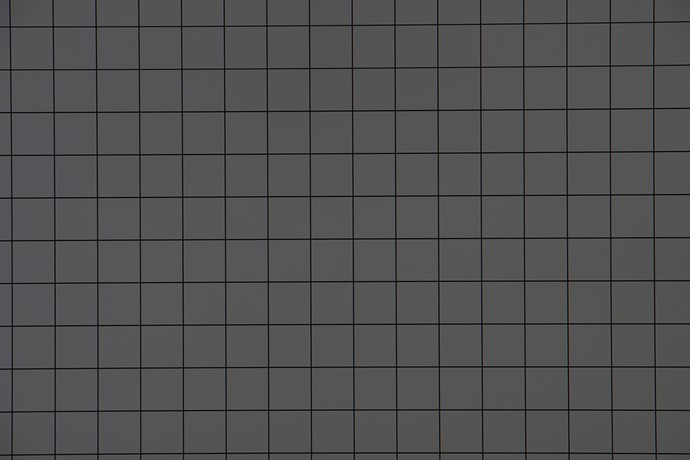
Or am I simply doing something wrong? I thought that using a photo like below would be able to give me a highly accurate estimation of the lens distortion, but maybe I am wrong. This is taken by placing my camera and lens perpendicular to my pc screen while showing a grid pattern.
And as an aside: would it be possible to automate the determination of the lens distortion parameters by analyzing the image above and doing some least squares analysis of the lines by comparing it with a reference grid?

