Hey guys,
Is there any way matching the lens distortion settings of blender’s camera tracker (k1, k2, k3)? Tried a lot to get the same result using nuke’s distortion model but it’s still off.
Edit: In the meantime I tried to re-implement Blenders (libmv) polynomal lens distortion model using shadertoy, in order to apply the lens distortion in natron by generating a STMap for that. I think I’m close, but when passing the same values k1=0.1 k2=0.0 k3=0.0 the resulting distortion is still too heavy in comparison to the distorted image out of Blender.
// Based on:
// https://www.shadertoy.com/view/lslGRN
// https://www.shadertoy.com/view/XdfGzH

vec3 color = vec3(0.4,0.4,0.4);
float lens = 24.0;

//note: period of 2, [-1;1]=/\
float sawtooth( float t )
{
    return abs(mod(abs(t), 2.0)-1.0);
}

vec2 BarrelDistort(vec2 p)
{
    float theta  = atan(p.y, p.x);
    float radius = length(p);
    radius = pow(radius, 1.2);
    p.x = radius * cos(theta);
    p.y = radius * sin(theta);
    return (1.0 * (p));
}

vec2 BlenderDistort(vec2 p)
{
    // https://en.wikipedia.org/wiki/Distortion_(optics)
    // https://github.com/sobotka/blender/blob/master/intern/libmv/libmv/simple_pipeline/distortion_models.h#L66
    float x = p.x;
    float y = p.y;

    float k1 = .1/2.0;
    float k2 = .0;
    float k3 = .0;

    float p1 = .0;
    float p2 = .0;

    float r2 = x*x + y*y;
    float r4 = r2 * r2;
    float r6 = r4 * r2;
    //float r_coeff = (T(1) + k1*r2 + k2*r4 + k3*r6);
    float r_coeff = (1.0 + k1*r2 + k2*r4 + k3*r6);
    //float xd = x * r_coeff + T(2)*p1*x*y + p2*(r2 + T(2)*x*x);
    float xd = x * r_coeff + 2.0*p1*x*y + p2*(r2 + 2.0*x*x);
    float yd = y * r_coeff + 2.0*p2*x*y + p1*(r2 + 2.0*y*y);

    return vec2(xd, yd);
}


void mainImage( out vec4 fragColor, in vec2 fragCoord )
{
    vec2 uv = fragCoord.xy / iResolution.xy;
    vec2 normalizedUV = (fragCoord.xy/(iResolution.xy/2.0))-1.0;

    vec2 dist = BlenderDistort(normalizedUV);
    vec2 uv_transform = vec2(.5)+vec2(.5)*dist;

    vec3 outcol = vec3(0.0);
    //outcol += texture( iChannel0, vec2(0,1)+vec2(1,-1)*uv ).rgb;
    outcol += texture( iChannel0, uv_transform ).rgb;


    // Draw Lines
    vec2 div = 30.0 * vec2(1.0, iResolution.y / iResolution.x );
    float lines = 0.0;
    lines += smoothstep( 0.2, 0.0, sawtooth( dist.x*2.0*div.x ) );
    lines += smoothstep( 0.2, 0.0, sawtooth( dist.y*2.0*div.y ) );
    lines = clamp( lines, 0.0, 1.0 );

    //outcol *= vec3(1.0-lines); //black
    //outcol += vec3(lines); //white

    //note: force black outside valid range
    vec2 valid = step( vec2(-1.0), dist ) * step( dist, vec2(1.0) );
    outcol *= valid.x*valid.y;

    fragColor = vec4( outcol,1.0 );


}
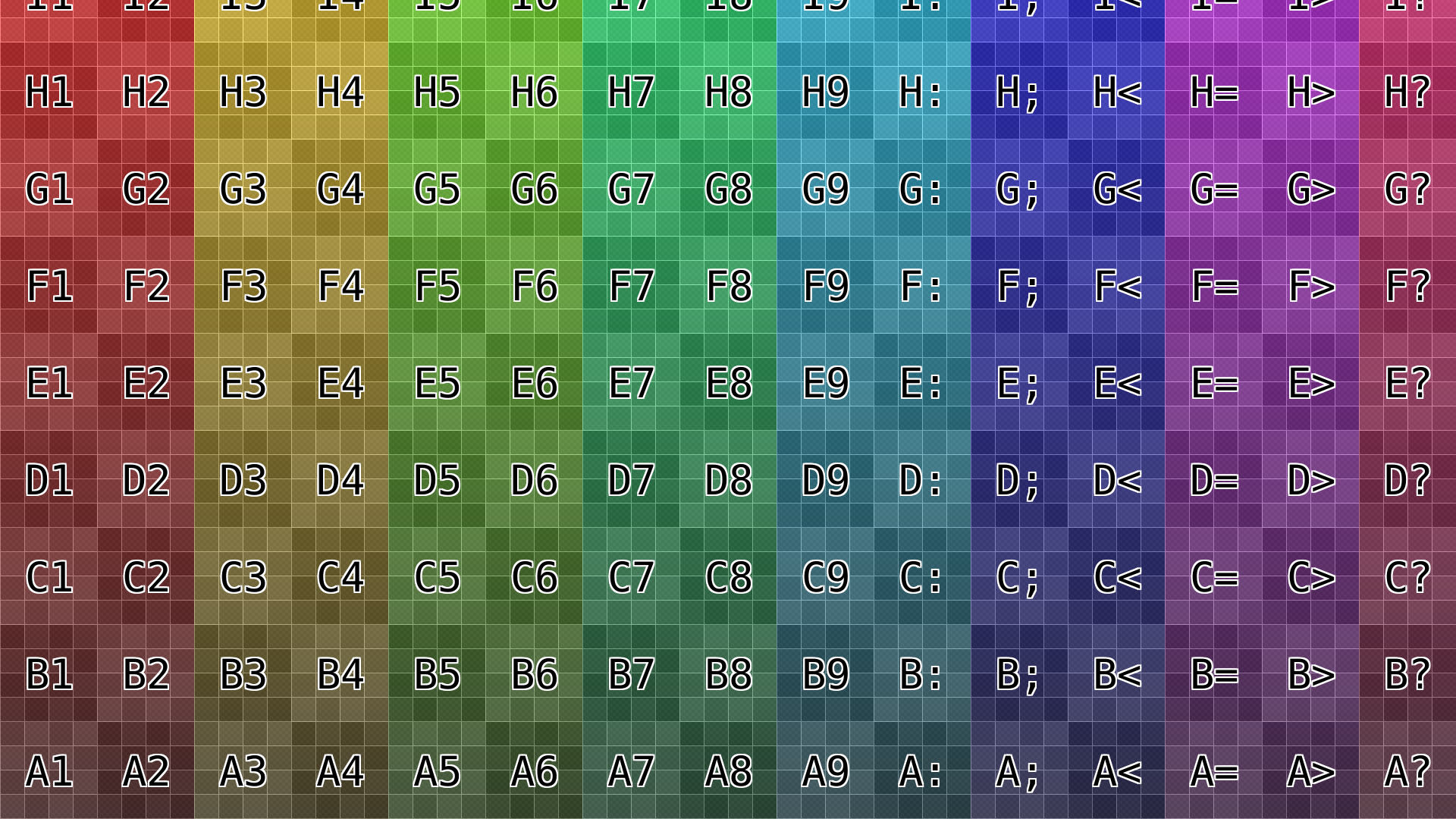
Test image undistorted
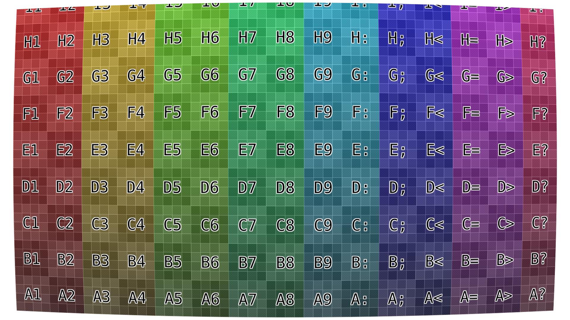
Test image distorted in Blender k1=0.1 k2=0.0 k3=0.0
I’d appreciate any help on that.
Cheers!
Josef