Don’t worry, if you do not have something ready at hand I’ll take some of my images and do some experimenting. Just wanted to see if you had examples that clearly show the possible artifacts… probably some sharp shot of tree branches might be a good candidate to see the staircase artifacts?
There might be an issue with the math parser version - it almost always has worse PSNR results than mine even in greyscale so I did a comparison; there are large differences within a 3 pixel boundary around the edges.
Repeating the tests after removing a 3px border for all images shows the math parser with better PSNR, but only a very small amount (~ 3x10^-6). With colour images it still does worse due to not averaging gradients sums across channels.
Edit: suspect the smoothing step in the wiki article may have the pixel values the wrong way round, need to compare properly with the paper / matlab example.
Can confirm the matlab source code doesn’t seem to match the wiki page as far as the “Smooth Area” sections are concerned (i.e. the wiki appears to be wrong). The weights match up but the interpolated pixel values are the wrong way around.
With that patched the k exponent actually affects output, I might have to add a slider for it since there’s more edge smoothing overall now. For now I’ve just patched the filter as it stands… will have to leave the rest for later.
Ah, that’s interesting !
Maybe I’m asking too much, but do you think the fix could be simple using the math parser instead (my version).
I’ll be interested to understand what differences it adds.
Anyway, I’m interested to put your faster version directly in the g’mic stdlib, if you agree with that idea.
Does it work when you have an arbitrary number N of channels ? Does it work for 3d volumetric images ? (i.e. just double the width and height of all planes ?).
Thanks!
The fix is very simple for both methods, if we take a sample from the math parser (I’ve omitted the boundary for brevity):
 DownRightPixel = (-j(-3,-3) + 9*j(-1,-1) + 9*j(1,1) - j(3,3))/16;
 UpRightPixel = (-j(3,-3) + 9*j(1,-1) + 9*j(-1,1) - j(-3,3))/16;
 DownRightPixel*weight1 + UpRightPixel*weight2
The quickest way is to switch the numbers of weight1 and weight2 but more correctly it should read:
 DownRightPixel = (-j(-3,-3) + 9*j(-1,-1) + 9*j(1,1) - j(3,3))/16;
 UpRightPixel = (-j(3,-3) + 9*j(1,-1) + 9*j(-1,1) - j(-3,3))/16;
 UpRightPixel*weight1 + DownRightPixel*weight2
Where we take “UpRightPixel” to be the 45 degree interpolated value. The same needs to be done for the horizontal/vertical pass. In the other method it’s a case of referencing two images the other way around so every bit as easy.
Arbitrary channels is easy enough, in fact only support for opacity changed that. What I should really do is have a “native” command which doesn’t care about channels/opacity, then for the g’mic filter split the opacity and call the native command on those. That has to be done because of gradient averaging across channels.
3d volumetric 
Hahah ok well without alterations it would work as is but with no interpolation between “slices”. Assuming you do a third pass in the depth plane it would be interpolating between previously interpolated values… it needs some thought!
Adding to g’mic stdlib is a great idea, but I still have cleanup to do. For instance I do a third unnecessary gradient amongst other things, it just made it much simpler to deal with in my head. If you fancy doing the tidy up for me though I’m more than happy 
I forgot to answer about the changes the fix produces! It’s mostly quite subtle but here’s a list:
More smoothing in general. Previously higher threshold gave more noticeable jaggies, due to the “Smooth Area” pixels being in the opposite direction from the edge.
Exponent k has more effect. It’s actually quite difficult now to see staircase without reducing k.
PSNR is improved. This is something I’ve never tried before so could well make mistakes; scale to 50% by nearest-neighbour and scale back up then compare after crop (since I now include the 1px removal) using g’mic -psnr. This is what made me spot it - decreasing k actually improved PSNR which made no sense.
Edit: I’d really like somebody to check what I’m saying! Especially compare wikipedia with the original paper/matlab source.
1 Like
I hope somebody can confirm this, but I now think the wiki page has another issue… the description of the horizontal/vertical gradient seems to be wrong.
The original paper appears to mention a 5x5 kernel with 7 absolute gradients summed in each direction. The matlab source also shows 7 subtractions per direction, whereas the wiki shows 9 in a diamond shape (within a 7x7 kernel).
This might explain some issues I’ve noticed: PSNR for the G’MIC filter being best around threshold 1.5, comparison with matlab test output images being ever so slightly different and there being quite a lot of edge smoothing in general.
It’s probably best to stick to the paper so I’m going to compare both (i.e. redo the filter).
That’s awesome you notice all these stuffs. Very surprising to see so much mistakes in the wikipedia page! Maybe it should be good to fix them also in wikipedia.
Is there some way to make this produce W2xH2 pixels exactly (even if just by duplicating a column + row?)?
have my eye on this to use as an antialiasing filter (DCCI 2x → scale down by a factor of 2 → smoothed image), but I currently am unable to avoid offsetting the result by half a pixel, which AFAICS is caused by having an input for the downscaling that is not an exact integer multiple of the target dimensions.
Yes, you’ll end up with a row at the right and bottom edges which has been interpolated with pixels outside the image boundary. As you say, duplicated edge would probably look best (i.e. neumann). I can add an option in the next version to allow that.
Bad news is it might have to wait a little, I now discover the matlab source has errors too - horizontal and vertical are swapped, but luckily swapped in all places so the final output is correct! Some of the math appears to be redundant too (taking ratio of reciprocal of gradient sums instead of just using ratio of gradient sums swapped).
I’m really glad I released this as “experimental” right now
Updated, changes:
- 5x5 H/V kernel (from original paper)
- Exponent slider
- Option to extend 1px
- -gcd_dcci2x operates on arbitrary channels, separate filter command now deals with opacity and values cut
Extra info:
- PSNR of 7x7 H/V kernel is frequently higher even though it’s not mentioned in the paper, might be worth having an option to allow it.
- Instead of 1/(d^k+1) I just use (d^k+1) and swap the values.
- Differences still remain between filter output and matlab examples, especially in low gradient (“smooth”) areas. Not sure why… PSNR now very close to values in the paper.
G’MIC math parser equivalent, without gradient averaging across channels: http://pastebin.com/9iU3sarw
2 Likes
Hello Andy,
I’ve integrated your code in the G’MIC stdlib. Thanks a lot, that’s really great.
Here are some examples and comparisons of what I get with this new upsizing algorithm:
The filter have been put in the Repair/ section of the G’MIC plug-in for GIMP:
<img src="/uploads/default/original/1X/a48e8f2c7349c41e12f0a0c2c7c5868404dd6f86.png" width=“690”
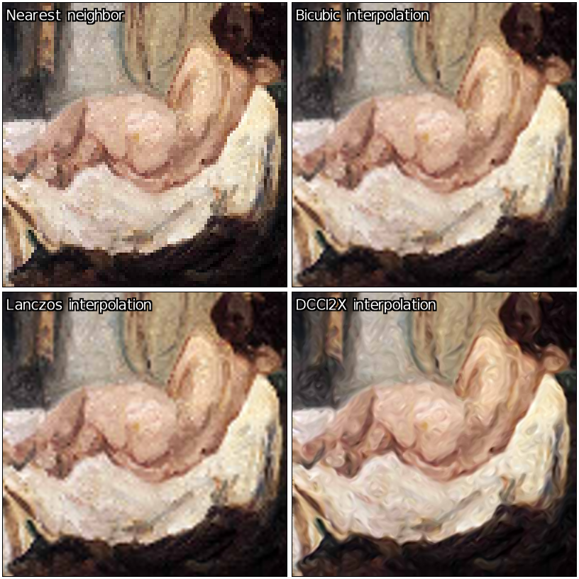
And here are a few results for x4 upscaling:
height=“409”>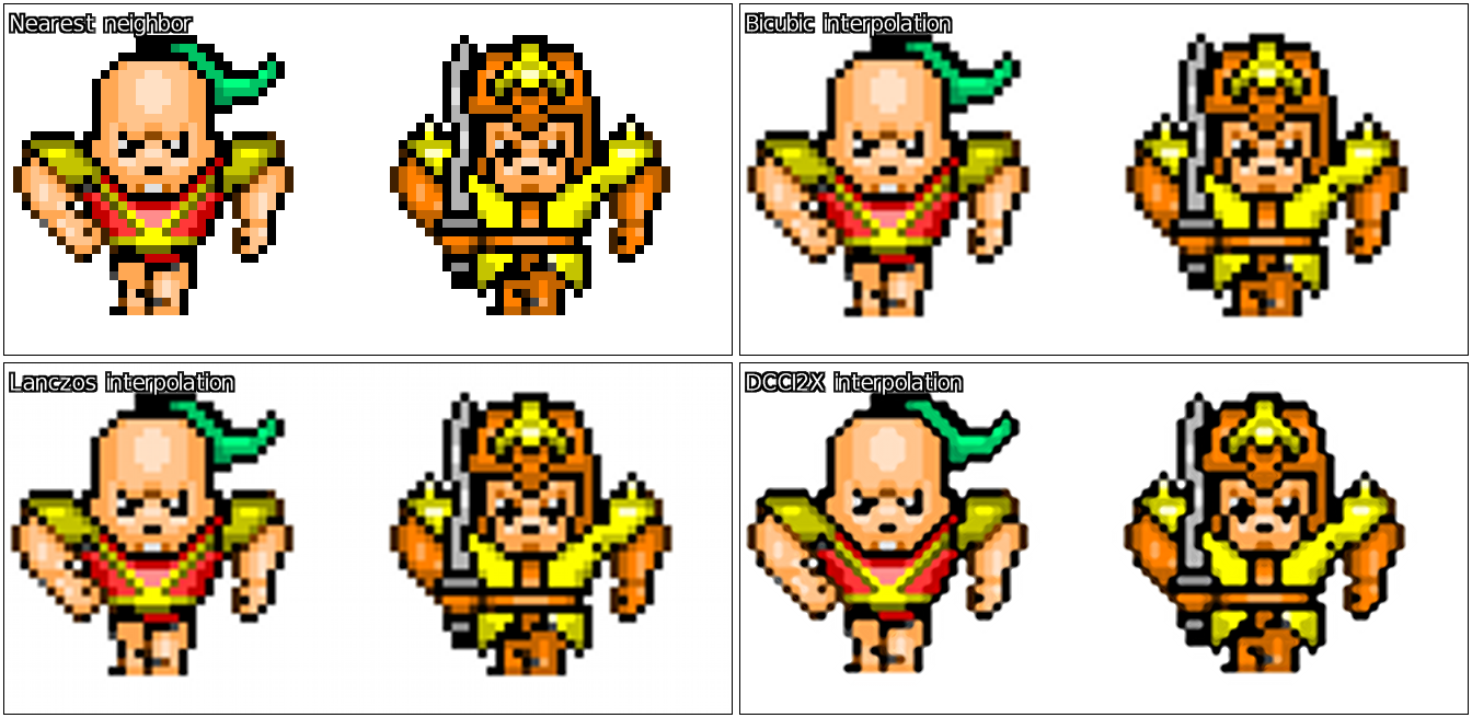


3 Likes
I was playing with this and had a thought.
Instead of interpolating between values, it would be better to estimate the sub-pixels that would make up each pixel if the image had been downsized.
So I came up with this to improve the dcci upscaling, or perhaps it is better called something like ‘targeted sharpening’.
--scale_dcci2x[0] $1,$2,1
--resize[1] [0],2
-sub[2] [0]  # find the differences between the original and the half-sized upscaled version.
-scale_dcci2x[2] $1,$2,1  # upscale the differences
-mul[2] -1
-add[2] [1]  # add them together
-rm[1]

# repeat but with image rotated 180 degrees to remove slight directional bias

-rotate 180


--resize[1] [0],2
-sub[2] [0]
-scale_dcci2x[2] $1,$2,1
-mul[2] -1
-add[2] [1]
-rm[1]

-rotate 180  # rotate back

-c 0,255

2 Likes
Hello
Great stuff in here!
I just wanted to ask that when you show demonstrations of what the algos can do, that you also use them on images which don’t suffer from JPEG compression artifacts. All of the photos from David’s previous post have such artifacts which makes the upscaling demonstration void, at least as far as I’m concerned (though of course some people will upscale JPEGs).
Hello! Suppose I want to upscale an image by 2.3x. Would it be then beneficial to use a DCCI-like method for 2x upscaling and then some other method like Lanczos or “no halo” for the additional 1.15x?
Thanks for providing all that!
Could be maybe better to do x4 first (two passes of dcci2x), then downscale to x2.3 afterwards.
Thanks! I’ll experiment with that as soon as I manage… as a bonus, with photoflow I should be able to provide 8x or even 16x DCCI upscaling with a negligible memory footprint, if that might interest you.
@Iain
Thought you might be interested in this one! That works quite well, although I do notice it re-introduces some “stair-stepping”. What you might want to try tweaking is the smooth/textured pixel part:
 _scale_dcci2x_smooth : -skip ${3=5}
 # calculate interpolated output for smooth areas
 -^[0,1] $3 -+[0,1] 1 --+[0,1] -/[0,1] [-1] -rm. # weights
 -pass$1 -pass$2 -*[0,-2] -*[1,-1] -+[0,1] # smooth
If you override that (obviously only in your own user file!) you can decide what happens to pixels in “smooth area” i.e. weak edges/textures. For example, to simply discard weights and just use 50% of each direction:
 _scale_dcci2x_smooth : -skip ${3=5}
 -f 0.5
 -pass$1 -pass$2 -*[0,-2] -*[1,-1] -+[0,1] # smooth
_scale_dcci2x_smooth is called with two images containing d1 and d2 summed absolute gradients from the algorithm, then passed the interpolated values as another two images:
[0] = d1, [1] = d2 initially
then after -pass$1 -pass$2:
[3] = downright/vertical interps, [4] = upright/horizontal interps
Hope I’ve explained that properly!
1 Like
I tried to implement DCCI myself but I have some problems. You mentioned that the description on Wikipedia is incorrect and the weights should be flipped when interpolating smooth areas. I did that but it still seems to be wrong:
Original:
http://puu.sh/ljsxW/0b197dbe52.png
Upscaled:
http://puu.sh/ljsxD/0e06c1f274.png
The edge looks jaggy and in the corners there are “stray pixels”. Of cause it could just be a bug, but I’ll get some sleep before I try to find out what causes that. I replicate the outer edges by the way. To be more precise: I use the nearest valid pixel when a pixel outside the bounds is being accessed. Also I calculate the edge weights by taking the average across all channels (except the alpha channel, because for now the images I use are always going to be completely opaque).
Do you have some example images? Original and upscaled with DCCI. And I don’t mean the ones posted here in previous replies, I mean plain png-files.
Also you refered to a paper. What paper is that? Where can I find it?
The paper is included (plus test png images) with the matlab example linked as a citation at the bottom of the wiki: http://www.mathworks.com/matlabcentral/fileexchange/38570-image-zooming-using-directional-cubic-convolution-interpolation
For smooth areas you want to interpolate mostly in the direction of the strongest edge, so for the diagonal case:
d1 = up right (45 degree) sum of abs gradients
d2 = down right (135 degree) sum of abs gradients
p1 = interp in up right direction
p2 = interp in down right direction
So if d1 is largest gradient, there’s a stronger edge in the down right direction and we want to interpolate mostly in that direction, so turning gradients into ratios/weights:
w1 = d1 / (d1 + d2)
w2 = d2 / (d1 + d2)
pixel = w1 * p2 + w2 * p1
But of course to deal with division by zero and control edge sharpness by exponent:
w1 = d1^k + 1
w2 = d2^k + 1
weight1 = w1 / (w1 + w2)
weight2 = w2 / (w1 + w2)
pixel = weight1 * p2 + weight2 * p1
The paper suggests using reciprocals to invert them but for ratios there’s no point because:
1/x / (1/x + 1/y) = y / (x + y)
1/y / (1/x + 1/y) = x / (x + y)