This is a sequel to this thread - Geometry Help - Rectangular Polar Transformation (From Cartesian or To Cartesian) [SOLVED OR NEARLY SOLVED]
Right now, I decided to rework on obtaining a faster version of rectangular-polar transformation, and after so many attempts, I failed to find a better versions that solves the drawbacks from the one in gmic-community/reptorian.gmic. Hence, the need to make a sequel thread to see if any one else can solve it. There are application such as perspective streak, and that is exactly why I invented this. The code can be found below:
Reptorian's New Rectangular-Polar Transformation Attempt
new_rep_recpoltrans:
skip ${1=0},${2=0},${3=0},${4=}
if $1<-1||$1>1 error "($1>=-1&&$1<=1)=0" fi
if $2<-1||$2>1 error "($2>=-1&&$2<=1)=0" fi

#$1 = X-Location of co-aligned vertices. The range is -1 to 1 where 0 is center of image. #
#$2 = Y-Location of co-aligned vertices. The range is -1 to 1 where 0 is center of image.#
#$3 = 0=From rectangular-polar to cartersian standard | 1=To rectangular-polar#
#$4 = Defines the orientation the before image was. This can only be used if $3==0#

repeat $! l[$>]
 ov=${-rep_2dcr}
 if $3
  maxlength={max(w,h)*1.5}
  perimeter={(w+h)*2}
  {$perimeter},{$maxlength},{d},{s},":begin(
    surface=expr('begin(const dpi=2*pi;);(x/w)*dpi;',w); #x-coordinates in rectangular-polar are defined as in 0-2*pi range#
    const dpi=pi*2;
    const ww=w#0-1; #Pixel coordinates limits are defined by 0-(width of first image minus 1)#
    const hh=h#0-1; #Pixel coordinates limits are defined by 0-(width of first image minus 1)#
    const ihh=h-1; #This is used to convert from cartesian to rectangular-polar y-axis to 0-1 range#
    const point_x=round((($1*-1)*.5+.5)*ww); #This takes into account of the fact that we're using pixel coordinates. Rounding is not needed in vector. Also used to find distance away.#
    const point_y=round(($2*.5+.5)*hh); #This takes into account of the fact that we're using pixel coordinates. Rounding is not needed in vector Also used to find distance away.#
    const inv_point_x=ww-point_x; #Find the distance away from the center#
    const inv_point_y=hh-point_y; #Find the distance away from the center#
    const cut_ang_s0=abs(atan2(inv_point_y,inv_point_x)); #Draw 4 triangles where the center contains co-aligned vertices. This defines the top triangle#
    const cut_ang_s1=pi-abs(atan2(inv_point_y,point_x)); #Draw 4 triangles where the center contains co-aligned vertices. This defines the right triangle#
    const cut_ang_s2=pi+abs(atan2(point_y,point_x)); #Draw 4 triangles where the center contains co-aligned vertices. This defines the bottom triangle#
    const cut_ang_s3=dpi-abs(atan2(point_y,inv_point_x)); #Draw 4 triangles where the center contains co-aligned vertices. This defines the left triangle#
    distanceaway=[ww-point_x,hh-point_y,point_x,point_y]; #Vector of distance away#
   );
   surface_angle=surface[x];
   surface_angle>cut_ang_s0&&surface_angle<=cut_ang_s1?side=1:
   surface_angle>cut_ang_s1&&surface_angle<=cut_ang_s2?side=2:
   surface_angle>cut_ang_s2&&surface_angle<=cut_ang_s3?side=3:
   side=0;
   mdist=abs(side%2?1/sin(surface_angle):1/cos(surface_angle));
   dix=(point_x+cos(surface_angle)*distanceaway[side]*mdist*y/ihh);
   diy=(point_y+sin(surface_angle)*distanceaway[side]*mdist*y/ihh);
   I(#0,round(ww-dix),round(diy),z);"

  k.
 else

  #The block below defines the dimension given orientation info#

  #Block Begin#
  $=val
  orientation=${val{$>+4}}
  perimeter={w}
  length_1={$perimeter-h*(4/3)}
  length_2={$perimeter-$length_1}
  if $orientation
   width={min($length_1,$length_2)}
   height={max($length_1,$length_2)}
  else
   width={max($length_1,$length_2)}
   height={min($length_1,$length_2)}
  fi

  #Block End#

  v + echo {w},{h} v -
  {$width},{$height},{d},{s},":begin(
   const ww=w#0-1;
   const hh=h#0-1;
   const nw=w-1;
   const nh=h-1;
   const sd=max(nw,nh)/min(nw,nh);
   const dpi=2*pi;
   const cx=.5+$1*.5;
   const cy=.5+$2*.5;
   const px=round(cx*nw);
   const py=round(cy*nh);
   const rpx=nw-px;
   const rpy=nh-py;
  );
  xpos=x-px;
  ypos=y-py;
  ax=1-(atan2(ypos,xpos)+pi)/dpi;
  ay_x=x>px?(rpx-(nw-x))/rpx:(px-x)/px;
  ay_y=y>py?(rpy-(nh-y))/rpy:(py-y)/py;
  ay=max(ay_x,ay_y);
  I(#0,ax*ww,ay*hh,z);
  "
  r2dx. 50%,6
  k.
 else error "$3|"$"3!=intnum[-3,2]"
 fi
endl done
For those who don’t know. Here’s how rectangular-polar coordinates looks like:

It’s hard to explain in words, but x-coordinate is defined by the position around the the rectangle, and the y-axis is defined by the distance from the center to the edge of rectangle. Well, something like that.
What does the mona lisa image looks like when you convert Cartesian coordinate to rectangular-polar coordinates?
Original:
$ sp monalisa

After converting coordinates:
$ sp monalisa rep_recpoltrans 0,0,1

Note: Please see above image to follow along.
The goal is to transform it back and have zero-loss of information. This is theoretically possible as you do have sufficient information. Achieving it is difficult which is why this thread exists.
With the new version which attempts to fix drawbacks (it didn’t and it’s even worse than the implementation in gmic-community/reptorian.gmic. Here’s the result.
Test result of new reptorian rectangular-polar:
$ sp monalisa +new_rep_recpoltrans 0,0,1 new_rep_recpoltrans. 0,0,0,1 +blend difference a x
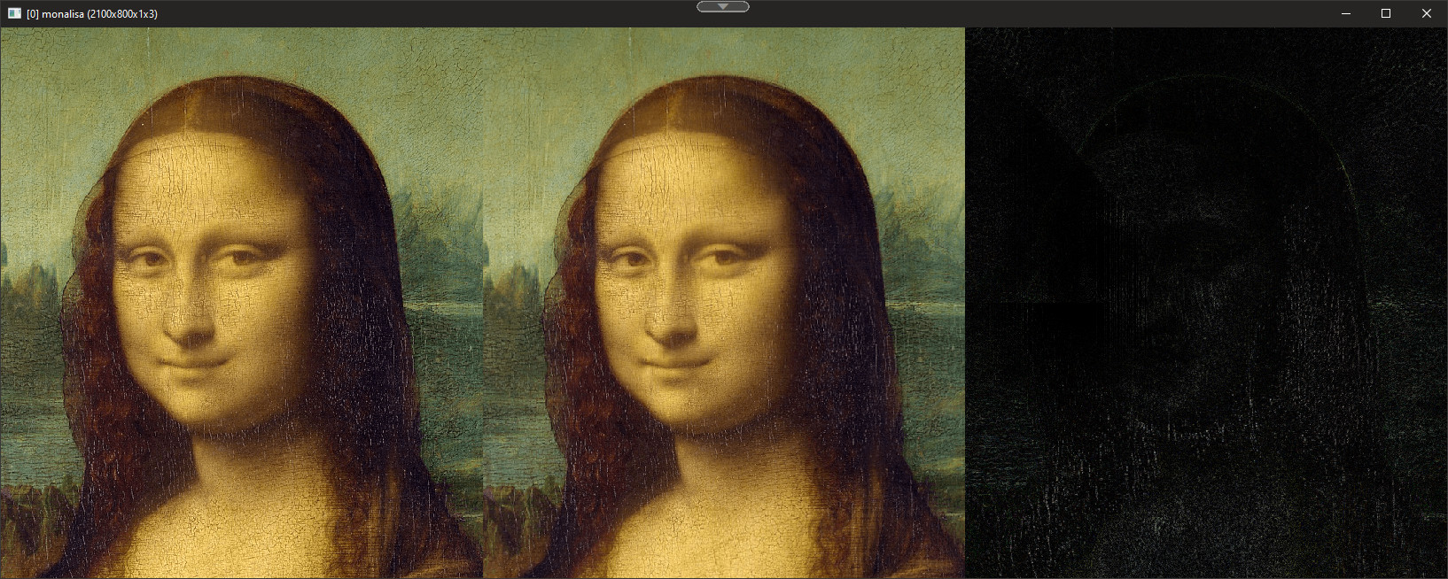
If you look closely on the dark image, it’s clear that there’s information loss between the transformation. This thread should be about solving the information loss while still being useful for applying filters such as axis streak.
There is a max difference of ~171.5. That is not good at all. On the upside, it is 5 times faster than the implementation in gmic-community/reptorian.gmic. That’s about the only drawback solved.


