That is the vision I get when I see stock photos with a generic attractive person.
1 Like
Now, I think the filter is ready now that Alpha processing works.
Is it possible to do something like this?
f[0] “i2((i#0/255w#0),(i#1/255w#1))”
There are 3 images in total. I want to change the i#0 image based on the value found in i#2(x,y). It’s kind of a blending mode, but you’re using images and coordinate instead of expression. The value represent x,y. The greater the value, the greater the coordinate.
P.S
Found it.
rv to_rgb[^0] f[0] "i(i#2/255*w#1,i#1/255*h#1)"
The above will blend the two image as if the image was the blending mode.
Now, I am going to try to convert values generated from my rep_reversespiralbwcoormap command into a formula based value since it is the only way to bypass dynamic array limitation of 4096^2. Yes, I kid you not on trying to convert 2 variable dynamic array into 1d function. It’s basically interconnected slope where height defines slopes close to 90 degrees.
That’s going to be very tough to do.
First I have to create two svg lines, then I have to analyze it and theorize until all in the clear. It the theorizing stage that’s going to be hard.
— Gave up on doing it, was taking too much of my time even though I believe my theory can work. Went to code in a output error message if dynamic array insertion stops working. It stops working after sqr(4096) or sqr(2^12). Ideally, (2^16)*(2^16) should be the limit if there has to be one. I may be back to another attempt after a month later.
Since the rep_reversespiralbwcoordinatemap command is on hold.
I worked on replicating nebulous Paint.NET plugin -
iw={w}
ih={h}
channels 0

if $iw>$ih r $iw,$iw,1,1
else r $ih,$ih,1,1 fi

f "
IX=(x/w-.5)*2; #Output Gradient that goes from value -1,1 from the left to the right#
IY=(y/h-.5)*2; #Output Gradient that goes from value -1,1 from the top to the bottom#
IX*=12*4;
IY*=12*4;
k=pi+1.5;
ang=270*pi/180;
ti=sin(atan2(IX,IY))*cos(sqrt(IX*IX+IY*IY))+k+sqrt(IX*IX+IY*IY)+ang;
g=(sin(ti)+sin(pi/2+ti)+sin(pi+ti));
"
n 0,255
modf 3,255,.25
negate
The surface this gives me is this -
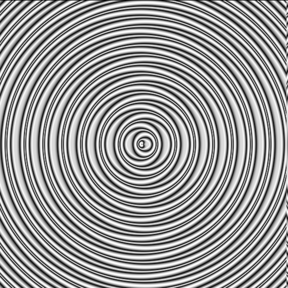
I’ll admit, it’s not exact.
PS. Never mind, I solved it. +k was supposed to be *k
Soon, G’MIC will have Nebulous Paint.NET plugin.
Code so far
iw={w}
ih={h}
channels 0

if $iw>$ih r $iw,$iw,1,1
else r $ih,$ih,1,1 fi

f "
IX=(x/w-.5)*2;
IY=(y/h-.5)*2;
IX*=12*4;
IY*=12*4;
k=pi+12/10;
ang=0*pi/180;
ti=sin(atan2(IY*-1,IX))*cos(sqrt(IX*IX+IY*IY))*k+sqrt(IX*IX+IY*IY)+ang;
g=(sin(ti)+sin(pi/2+ti)+sin(pi+ti));
"
+ 1 * 128
The surface looks like this - Exactly like the PDN version
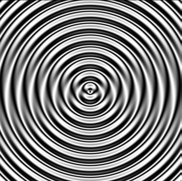
2 Likes
The first image gives me the CD effect when I scroll up and down. Very fun.
Any idea on how I can solve the distortion offset? It been getting on my nerve.
#@cli rep_nebulous: _rings>0,zoom_scale_x>0,zoom_scale_y>0,-100<=x_center[%]<=100,-100<=y_center[%]<=100,0<=_fxyangle<=360,_wave,0<=_lighting_angle<=360,_disturbance>=0,_distx,_disty,_subpixelevel,0<=_subpixelprocessingmethod<=4
#@cli : Default value: 'fxyangle=0','wave=1','lighting_angle=0','disturbance=0','distx=0','disty=0','subpixellevel=2','subpixelprocessing=1'
rep_nebulous:
skip ${6=0},${7=1},${8=0},${9=0},${10=0},${11=0},${12=2},${13=3}

if $1==0||$2==0||$3==0 v + error "Zoom scaling variable cannot be zero!" fi
if $9<0 v + error "Disturbance factor cannot be less than 0!" fi

iw={w}
ih={h}
channels 0

if $iw>$ih r {$iw*$12},{$ih*$12},1,1
else r {$iw*$12},{$ih*$12},1,1 fi

f "
sd=w/h;
shx=($4*w)/2;
shy=($5*h)/2;
ang=pi*$6/180;
ix=((x+shx)/w-.5)*2/(h>w?1/sd:1);
iy=((y+shy)/h-.5)*2/(w>h?sd:1);
IX=ix*cos(ang)-iy*sin(ang);
IY=ix*sin(ang)+iy*cos(ang);
IX*=$1*4*(1/$2);
IY*=$1*4*(1/$3);
distlvl=$9;
dist=pi/(distlvl/100);
disth=$10;
distv=$11;
cx=x-w/2;
cy=y-y/2;
IX+=distlvl>0?(disth*(sin(((cx/10+cy/10)/2)/dist)-cos(((cy/10-cx/10)/2)/dist)));
IY+=distlvl>0?(-distv*(sin(((cx/10+cy/10)/2)/dist)+cos(((cy/10-cx/10)/2)/dist)));
k=pi+((-pi+(pi*$7))*10)/10;
ld=$8*pi/180;
ti=sin(atan2(IY,IX))*cos(sqrt(IX*IX+IY*IY))*k+sqrt(IX*IX+IY*IY)+ld;
g=(sin(ti)+sin(pi/2+ti)+sin(pi+ti));
"

if $iw>$ih r $iw,$ih,1,1,{$13+2}
else r $iw,$ih,1,1,{$13+2} fi
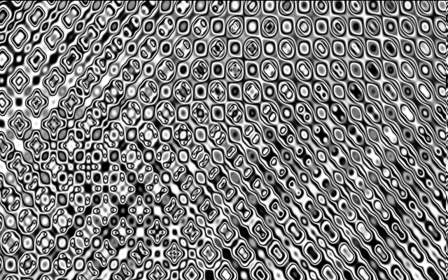
When I do +rep_nebulous 12,1,1,{300/2/w},0,0,1,0,10,30,0 n 0,255
blend difference
I noticed that there might be a way to solve the distortion offset. You see a relationship between some variable here?
Figured out distortion displacement. By the way, I got this from the cli I’m working on.
The PDN result

1 Like
Ready for testing now.
https://github.com/dtschump/gmic-community/pull/176/files
@afre How do you feel about the order? I’m not too sure about it. Depending on your answer, if the order is bad, then I"ll change it. It doesn’t behave exactly like the PDN version, but I tried my best anyway and it works, and that is what matters. I’m satisfied with it regardless.
@David_Tschumperle Mentioning you since I didn’t want it to be pushed until the order is ok.
P.S. Result

1 Like
I think the parameter order of the PDN version makes more sense.
I am still learning how to use GitHub. When I made my first pull request, I noticed that one could do a draft that cannot be committed.
I don’t think I’ll change the placement of color seeing as it does affect the visual, and it’s more intuitive for CLI users to have color option in front than in the back. But, however, what you’re saying is that X and Y shift placement should have less priority than wave and lighting, right? Should f(x,y) angle have a higher priority than wave and lighting? I guess it should go like this -
- Grayscale or Color
- XY Factor
- X Factor
- Y Factor
- Disturbance Main
- Disturbance X
- Disturbance Y
- Function Angle
- Wave Count
- Lighting Angle
- Shift X
- Shift Y
- Subpixel Scaling
- Subpixel Scaling Method
Since I am unfamiliar with this filter, I have no idea; but reading the PDN post with the parameter descriptions convinces me that the author had the right idea. I think the best way to find out is to make a GUI version and put it in Testing for people to try.
Personally, I wouldn’t place Grayscale or Color as #1, as it is a binary choice. I would place range parameters first. However, as I said above, I won’t know unless I have a more hands-on GUI to play with.
Deleted earlier post as Nebulous filter is on G’MIC now.
I’ll post this code for the night and let people give a guess of what I’m doing. And yes, it is going to be inspired by yet another Madjik Paint.NET filter.
autocrop_components ,,,, rm[0] a x
Hint: This would be applied to every rows or column. It creates a distortion effect.
– EDIT –
Got a working code though it’s a pretty simple version. No alpha threshold support, and no way to determine how much influence rather than position. The alpha support should be simple to implement. The influence factor on the other hand…
#@cli rep_sptbwgp: (eq. to rep_shift_pixel_to_boundary_with_group_pixels)
rep_sptbwgp: rep_shift_pixel_to_boundary_with_group_pixels $*
#@cli rep_shift_pixel_to_boundary_with_group_pixels: _axis={ 0=Horizontal | 1=Vertical }, 0<=_position<=1
#@cli : Shifts pixels to boundary by percentage using grouped pixels. position less than .5 means shift will be negative, and position greater than .5 means shift will be positive.
rep_shift_pixel_to_boundary_with_group_pixels:
repeat $! l[$>]
iw={w}
ih={h}
dir=$2

if $dir<0||$dir>1 v + error "Exceed the boundaries!" fi

if $1
s x
repeat $! l[$>] r 1,{h+1},100%,100%,0,0,.5,1 autocrop_components ,,,, a y r 1,$ih,100%,100%,0,0,.5,$dir endl done
a x
else
s y
repeat $! l[$>] r {w+1},1,100%,100%,0,0,1,.5 autocrop_components ,,,, a x r $iw,1,100%,100%,0,0,$dir,.5 endl done
a y
fi
endl done
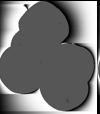
Input Image

Output of rep_sptbwgp 1,1

rep_sptbwgp is an interesting name. That is one sad test tube. 
Now, I think I have a idea on how can I change the influence factor. It involves the mix of streak, and negative values. Negative values would be erased after the shift. Streak would be used to create a linear gradient. Then after the streak is done, apply if less than value, then add into original pixel using negative value. Then apply the distortion, and after that, erased negative value.
I don’t remember if this was you, but didn’t you coded a one direction motion blur? I believe I am going to need it. That would provide the easiest solution to my problem though it has it limits compared to the streak approach, but certainly the easiest way to go. Maybe a mixed approach would be fine. Using one direction motion blur to define which one is left side, and which one to right, then use streak. Then change it to negative number which minimum value is less than epsilon avoiding the last channel. And then I might have to use a threshold to define which one to keep, and which one not to keep. After that, apply distortion, and then erase all value with negative value to 0.
It can be found in Exercises in two places but it is very tentative. From what I can remember, it has more to do with shapes than a more generalized blur. Best program your own in isolation. 
Interested to see what you come up with because I would still like to have a handy way of doing it.
You could look into my fragment blur code. If you manipulate the opacity, you will find a one direction motion blur. I found this solution to generate what I would like to use for my gravity replication project. I did replicated pdn gravity, but only adding influence to it.
iw={w}
ih={h}
threshold=128

f "i3" s c a[0-2] c em.. 0 autoindex.. 3,0,0 n.. 0,255 a c f s==2?(i1<=$threshold?0:i):(s==3?(i2<=$threshold?0:i):s==4?(i3<=$threshold?0:i):s==5?(i4<=$threshold?0:i))
+f. "G=x/w*255;[255-G,255]" +f. "G=x/w*255;[255-G,255]" rv[0,1] a x to_rgba fx_streak 0,0,0,0,0,0,3 remove_opacity r $iw,$ih,100%,100%,0,0,.5,.5
Maybe this should it own filter, what do you think?
Definitely but I am not satisfied with the result in your sample image. Could you do a directional blur on an image of polka dots?
The shift is a bug from copy and pasting from Krita to Firefox. Here’s the bigger result using image at another forum.
I guess it’ll be it own filter then.
Nope, doesn’t look natural at all, just a bunch of gradient ramps.