Earlier post has been removed: Not needed anymore.
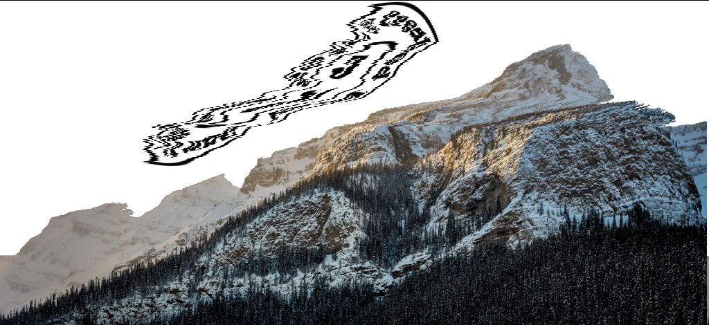
I have finished my filter though it’s not quite perfect. It has it own series of issue with influence factor. Anyway, it’s the best I can do.
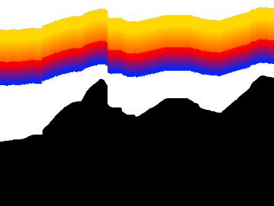
The above use influence factor of .5 and downward shift.
Earlier post has been removed: Not needed anymore.
I have finished my filter though it’s not quite perfect. It has it own series of issue with influence factor. Anyway, it’s the best I can do.
The above use influence factor of .5 and downward shift.
For David: I have a question for you, is rounding applied on the streak filter? The reason I’m asking this is because I don’t know exactly why the influence factor still lead to undesired distortion(lines going off in the wrong place) on my gravity-based filter (glitch artists might see it as desirable though). Maybe if it wasn’t rounded, the distortion would be gone. Then again, as you said, it needs better algorithm to get around that, and speaking of which, while on fill might be the solution to the reverse spiral matrix, I just figured how it works, so I can fix it a week later. Another question, how do you replace vector value using existing matrix? Dar_elt?
For both: Also, my theory on fixing it would involve making a contour only on series of edge that is closest to boundaries. Mirror the contour. Apply the distortion on the coordinate map (image containing numbers to define coordinates just like I did for spiral matrix) using the gravity-based cli. Crop to just coordinate map data. Any idea.
I really don’t know two-thirds of the stuff you are talking about. I often smile and nod and make a few seemingly intelligent remarks.  I need an explanation a simple person like me can understand.
Ok. I’ll expand on my explanation. Right now, I would like to create a smooth transition of pixels.
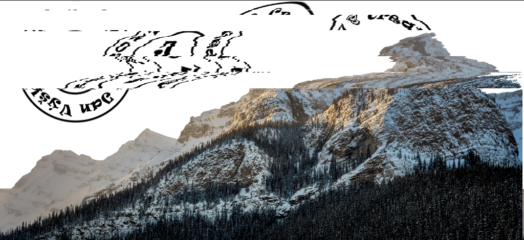
Source of picture - Pexels-photo-630791 by Vyskaj on DeviantArt
From this
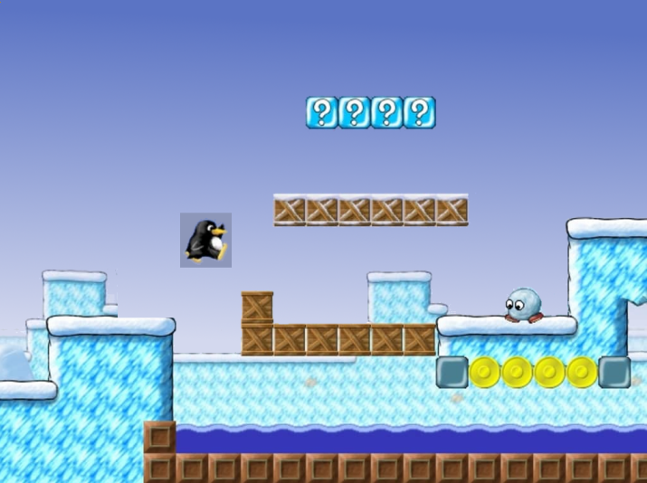
With influence factor, I have this issue -
Wow, would you look at that? That’s with linear blur approach. The other approach is to use streak formula.
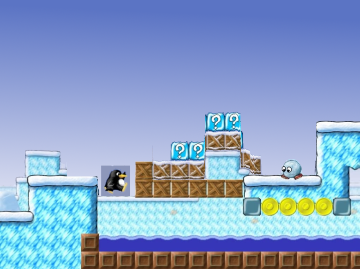
With max influence factor, I get this -
I’m not so sure how to get around this obnoxious issue. It only gets worse with images that has a lot of alpha variance. See my g’mic community commit to see how streak approach would look like when influence is enabled.
There is still not enough info. My guess, by “smooth transition”, you mean that you want the objects to morph or interpolate into one another?
Yes, I mean by morphing. Right now, anything between 0 or 1 has erratic morphing when slider is changing or value is changing.
I have something vague in mind but I don’t know if it is what you want. I need to see what you have in easy to understand steps first. 1. 2. 3. etc.
This might be a tangent but I am reminded of them fun screensavers that used to have neat animations. Might look simple but they might reveal some insights as to how pixels migrate. Also, @bazza seems to have a thing for warping, morphing, animation and old school stuff. Also, see Inkscape and how Interpolate works, though it is for vector shapes… Just brainstorming here.
It is very interesting as they fall the things surrounded by transparency. As you do to see the intermediate steps?

Do you mean like a convolution?
Example gmic run "sp tiger (1,0) r. 100,1,1,1,3 convolve.. ."
Now that’s a better solution. But now with autocrop and autocrop_components, I was thinking on the line of using weighted average between full influence and 0 influence. I thought this was going to be easy to use value from autocrop_components, but apparently not. I’ll attempt with multiple clis to do this.
Yes, convolve is a good idea, just need to make it region and structure (or object) aware. Have fun with that @Reptorian!
Perhaps what you really want is a different convolution kernel per line?
If so, a “cheap” way might be to blend a fully convolved image in. Otherwise, you could split the image along the y axis and loop over the images (rows) with a separate convolve (G’MIC is probably fast enough if you keep the loop content small!). Alternatively, you could do everything manually within the fill command - perhaps using crop() and avg() etc.
Yes, different convolution kernel per line is exactly what I want. That’s what exactly the streak formula does.
To give you a hint, maybe something like this:
gmic sp tiger 100,[0],1,1,u f.. "K=crop(#-1,0,y,0,0,w#-1,1,1,1,1);dot(K/sum(K),crop(x,y,z,c,100,1,1,1,1))"
And if you want the kernel to cover more than one row, just alter the crop area (so long as total size w*h matches):
gmic sp tiger 100,[0],1,1,u f.. "K=crop(#-1,0,y,0,0,w#-1,1,1,1,1);dot(K/sum(K),crop(x,y,z,c,25,4,1,1,1))"
That’s with a random “list of kernels” in one image, obviously that needs to hold the kernels you want instead.
Tiger motion sickness. 

EDIT: Success! Influence to 0 change nothing, and influence to .5 shows a smooth transition, and influence to 1 is full effect.
Thank you for your support of helping! @afre @garagecoder
iw={w}
ih={h}
is={s}
ws=1
axis=0
threshold_var=0
influence_var=.5
shift_var={($ws+1)/2}
dir={$axis?($ws>=0?1:-1):($ws<0?1:-1)}
s c

l. alpha_max={iM}
alpha_middle={iM/2}
endl

f. $threshold_var>0?($threshold_var==1?(i<(1-10^-8)*$alpha_max?0:i):(i<$threshold_var*$alpha_max?0:i)):i
a c
+channels {$is-1}
f. i==0?0:$alpha_max
if $axis
+shift. 0,$dir negate.
else
+shift. $dir,0 negate.
fi
+add[-1,-2]
/. 2 rm.. rv[^0] a[^0] c
l.

+select_color 0,$alpha_middle,0
f.. "
const step = max(1,0%*min(w,h));
const angle = (0*90)*pi/180;
const dx = step*cos(angle);
const dy = step*sin(angle);
if (!i(#-1),I,
ixf = xf = x; iyf = yf = y; lf = 0;
while (i(#-1,ixf=round(xf),iyf=round(yf)), ++lf; xf-=dx; yf-=dy);
ixb = xb = x; iyb = yb = y; lb = 0;
while (i(#-1,ixb=round(xb),iyb=round(yb)), ++lb; xb+=dx; yb+=dy);
(lb*lb*I(ixf,iyf) + lf*lf*I(ixb,iyb))/(lb^2+lf^2);
)"
channels 0
f.. "i#0==i#1?1:i"
rm.
f $influence_var>0?($influence_var==1?(i<(1-10^-8)*$alpha_max?0:i):(i<($influence_var*$alpha_max)?0:i)):i
f i!=0?i+$alpha_max
endl
s c
l[-2,-1] f.. "i==0?i#1:i" endl
rm.
a c

if $axis>0
s x
repeat $! l[$>] r 1,{h+1},100%,100%,0,0,.5,1 autocrop_components ,,,, a y r 1,$ih,100%,100%,0,0,.5,{1-$shift_var} endl done
a x
else
s y
repeat $! l[$>] r {w+1},1,100%,100%,0,0,1,.5 autocrop_components ,,,, a x r $iw,1,100%,100%,0,0,$shift_var,.5 endl done
a y
f "s==2?[i0,i1<0?0:i1]:(s==3?[i0,i1,i2<0?0:i2]:s==4?[i0,i1,i2,i3<0?0:i3]:s==5?[i0,i1,i2,i3,i4<0?0:i4])"
fi
s c
f. i>$alpha_max?0:i
a c
EDIT: Looks like center positioning has issues with influence. Elsewhere, it works fine. Perhaps I may have to create dynamic row/column on the two side to take into consideration of positioning. That way, it’ll look balanced.
Pretty good but still not satisfied.
What I had in mind were concepts such as distance, watershed, least-cost, collision, contours and boundaries.
If you don’t want any blurring, then why not use warp? That way you get “free” interpolation…
The thing is I don’t know how to get similar result using warp.
Ah, that’s a pity - warp is very fast too. You need two images - an input image and a warp vector map. Each “pixel” in the map image is not really a pixel; it’s more like a reference - it points to where to get the pixel colours from. Example:
gmic sp tiger +f "[x,y,z]" mirror. x +warp[0] [1]
Notice the mirror is done to the map, not the image!