Absolutely. Chuck a fulcrum in there for a particular value, and you have some terrific control.
Indeed. As long as it comes after the log transform. The only slippery part is remapping the log’s middle grey code value to the aesthetic transfer function’s code value appropriate for the display in question.
Well, that’s doable with eye appreciation on a calibrated screen, isn’t it ? At that point in the process, you might want to get some creative control over the picture, otherwise it’s just technical processing.
That sounds great but you have said earlier this plugin is not linked to real word coming after exposure, … then I don’t succeed in understanding what is really done.
The calculated output is:
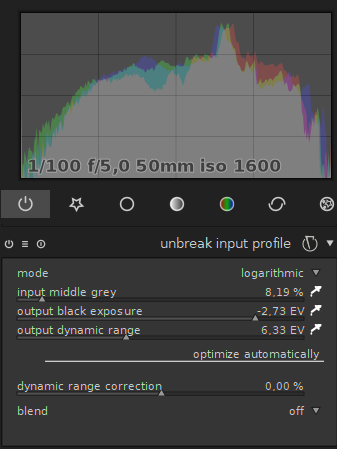
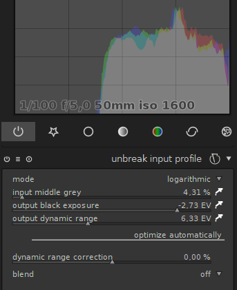
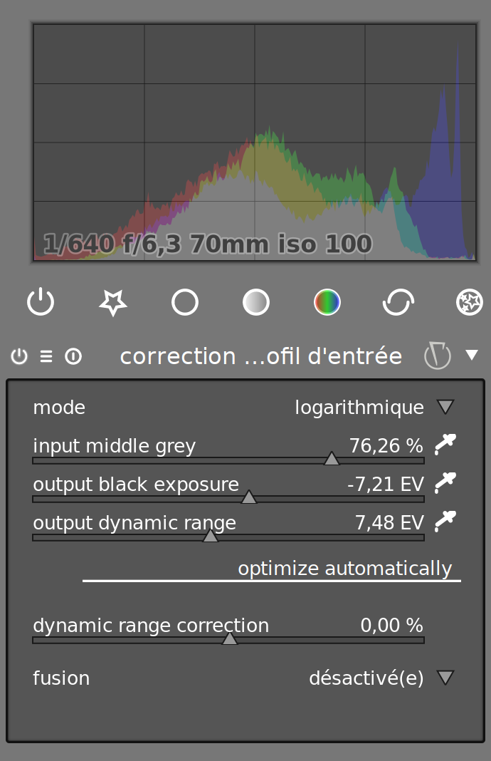
But when I move the grey point the histogram shows that I actually change the dark point (and dynamic range) which is counter intuitive. See:
You offer 3 settings, but there are only 2 independent variables.
Your maths must be a bit different from the one above.
Moving the grey independently should move left or right the middle pic without moving the borders.
It is necessary to be able to set the grey point, I agree totally, independently of black and white point.
The middle grey slider doesn’t do it as expected.
Your CDL stack should be the right place (slope/offset/power), shouldn’t it ?
Absolutely. It is just a matter of having a reasonable entry point. Given the normalized log ends up with a middle grey point at an arbitrary position depending on the dynamic range in question, this can be a little tricky to map for starting out.
No, what I said (or meant, I don’t remember what I said) is it not linked to the theoric dynamic range of the sensor (its bit-depth). But it is linked to the actual scene lighting, given you didn’t adjust the exposure earlier in the pixelpipe, before this module.
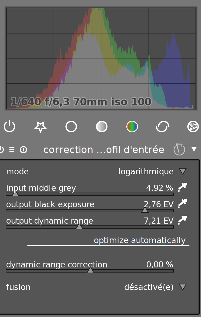
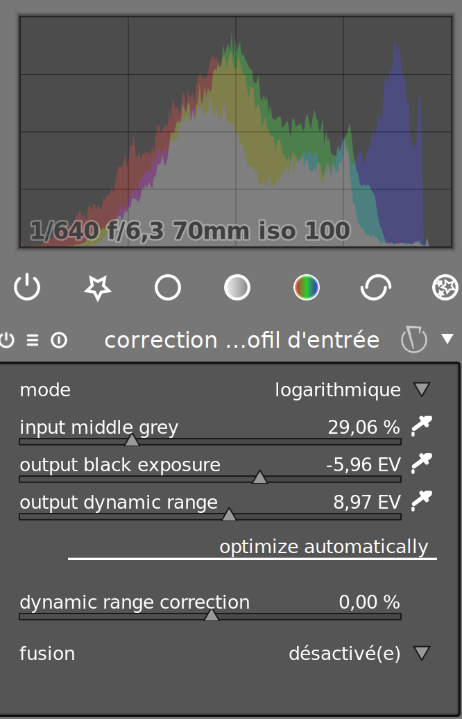
Ok, after moving the grey value, try moving the black point accordingly, and then the dynamic range. Your histogram should have a different shape. It’s not just a matter of limits. What the grey point does is allowing you to shape the distribution of luminances. What you look at are only the limits of the histogram.
See the how the relative height of the blue peak in highlights evolves, compared to the grey/red peaks height in the middle ? The grey level sets how much you want to squeeze the histogram towards the center. Then, the dynamic range is the rescaling factor, and the black exposure is the offset.
is what happens when you use the color-picker in auto mode. Which is a fair guess, but not always a good one. That’s why you can manually hard-set the dynamic range and black exposure, making this equation a simple (log2(input / grey) - black) / dynamic_range
This one is not intuitive at all … And I’m able reproduce the histograms obtained with grey level 4%, 40% and 100%, keeping it at 18% just playing with the 2 remaining sliders.
This means that the grey slider is useless.
The posemeter should be able to provide dynamic range EV and black EV. But I don’t see how I could use the shot of grey target…
Don’t worry if you don’t want to remove the grey slider (and some bits which work with it), I’m still happy, the 2 others do very well the job. And thank you for your patience and given explanations.
There is another topic which is of interest, the plugin used as a preset. It should have an automatic logarithmic mode (in the sense of the exposure plugin). No need to click on color picker. Could work with black point and white point corrections, depending of the type of shot … a wonder.
If you are able to reproduce the same histogram, no matter the grey level, it means that your picture is already well-balanced and probably doesn’t need this module. But in general, with HDR pictures, it is not the case.
You shoot the grey target, adjust the dynamic range to fit your posemeter measures, then use the color picker to get the average luma of the target, and duplicate this setting to all your pictures from the same lighting conditions.
That’s a tricky one because of the noise levels and such. I tried to do that, but the automatic detection is not 100 accurate (the minimum luma is not always the true black point), so having an auto mode that works 50 of the time is just an argument given to people to say opensource is crap.
Well, I value your feedback since it gives me a hint of how users will understand the module.
If you could share the image you have used to show the slippage I would try to remap the histograms as I did for my own picture.
EDIT. In fact that’s simple. I’m able to reproduce the same histogram with any value of grey just in changing the black point. I haven’t the non well balance image you talk about but I don’t see why the behaviour would be different.
Some maths to demonstrate it.
out = (log2(input / grey) - black) / dynamic_range
This is valid for all inputs (well balanced or not, clipping aside)
I understand that grey value is introduced in the equation merely to transform the input into stops but doesn’t transform the shape of the log.
I’m afraid I cannot do better to convince you that 2 inputs are enough to define a portion of log curve (as for a portion of line) and the grey slider is useless.
This could be similar to the point I made above; the grey level is there to be able to keep consistant output values between frames/images (where you would choose a particular grey and stick with it). So even if your input domain changes you still get the same output value for a similar grey. Yes you can calculate it and add, but that’s the reason: you would have to calculate it.
The consequence of choosing the grey point in the middle of the distribution as @Aurélien suggests is to ensure that dynamic range can be expressed as [-x,x] stops domain (centred).
But as the plugin works with any grey value, it can be constant, let’s say 18%…
Indeed, I agree it’s largely pointless for a single image. But the CDL spec is about transfer of parameters (10 in total) and data between devices/applications… I suppose it depends how closely that’s being followed here. It’s probably also about presenting controls/values people are familiar with, which I’m definitely not!
Edit: just to add the grey level setting I think originates from ACES, CDL makes no mention of it since it’s meant to work on linear or log signal.
What color space is the image in when it’s made linear?
My apologies for asking - I sort of like how the final algorithm looks on a test image so I’m trying to follow along with what you describe. But the camera input profile itself is already linear, so I’m guessing the color space that’s linearized is Lab space?
I know there is filmic, but it happens I’ve the nostalgy of unbreak.
I feel sometime a bit limited by the sigmoidal curve. In that case I would go back to unbreak.
But unbreak misses the input grey → output grey relationship that has filmic.
Would it be interesting, possible to add this to unbreak ?