@RawConvert I believe that there will always be “issues” whenever you compress the dynamic range. Try exporting a neutral profile image from RT and try manually taming it using 1-2 curves. It isn’t easy, at least for me!1
I haven’t used either version of the shadows-highlights tool, but based on what I have read, its improvements are substantial.
PS1 Lately, that is what I have been doing with my recent PlayRaws. The results don’t get a lot of likes but I have been hard at work experimenting on ways to tame the dynamic range and making everything super clean. That is why I ask the reader to zoom 100% to see the difference. I use simple curves and other simple ideas, so it isn’t like I am doing anything crazy like what others are doing with the venerable RT, DT, GIMP, etc.
hi afre, I don’t see why. You can compress using simple scaling or a decently-smooth curve, and I don’t think that could ever cause artefacts like banding or noise - as it seems you are finding!
You may think it’s pernickity that I’ve gone on about this, but lots of people spend lots of hours using RT, DT, etc and I’m sure everyone, especially the developers, want the apps to be as good as possible. Being aware of shortcomings and possible bugs can only be a good thing, even if they can’t be fixed for whatever reason.
Is there a case for more organised testing? Should some or more of us users work more closely with developers to test changes?
I’d love to have a pool of sample RAW images that are particularly suitable for testing shadows/highlights adjustment and dynamic range compression in general (actually, I believe the two things are the same). I am also doing some work with edge-aware blur filters and dynamic range compression, and it would be great to be able to directly compare results. I am mostly playing with the concepts and examples provided here.
Yes and the banding shifts if you change the tonal width. The raised shadows doesn’t quite reach the lowered highlights that is why there is a wider stripe.
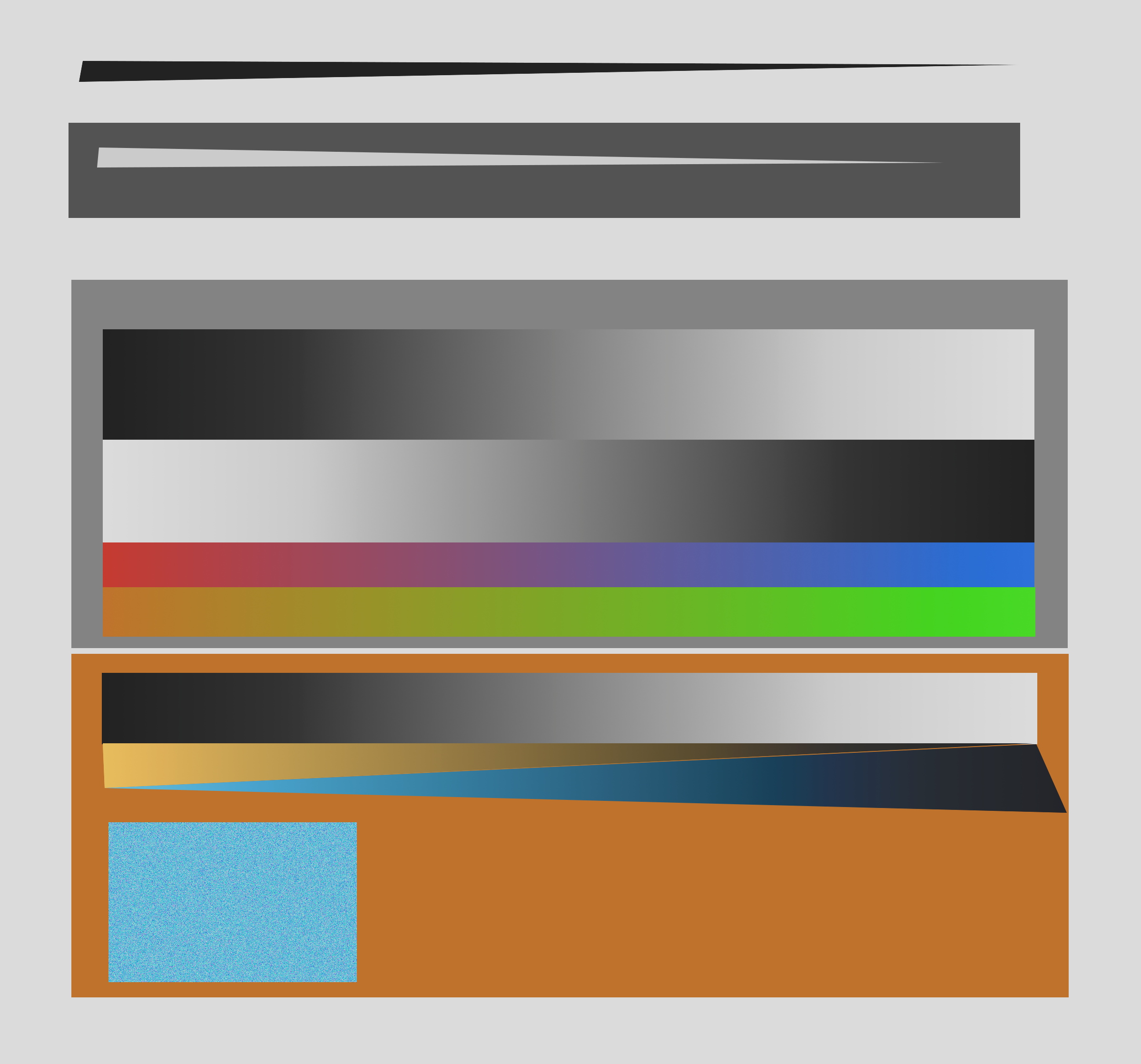
What I find strange is what happens in the raised shadows:
Original picture was a jpg gradient, white on the left and black on the right.
See the black pixels they stay black for some reason when raising the shadows. The halo on the dark end comes from raising the radius. Which means he seems to detect an edge there?
I have no direct experience with the bilateral filter, but I’m a huge fan of the (fast) guided filter. It’s a simple, efficient, and yet extremely powerful tool. It can be implemented in a few lines of code, and has many interesting applications, not just dynamic range compression (e.g. also dehazing, denoising, feathering, detail enhancement… see the paper for examples). Here is a little demo of some of its possibilities (note, this is my “playground” version of RT, it’s not in the official repo):
I’m also very much interested in this option, as I still have few “theoretical” difficulties with the bilateral filter and its proposed optimizations (in particular those that rely on image down-sampling).
Could you point me to the relevant file for the fast guided filter in RT?
Thanks!
P.S: could you remind me in which post I can find the picture your are using in your video? Thanks!
I LOVE the guided filter. I use it and link it whenever I have an excuse to do so. A lot of sophisticated applications and derivatives have been researched since. At its worst, it performs as well as the bilateral but is faster and simpler. … At least that is what I have read and experienced so far.
There’s some similar stuff here to my “Tone Enhance” filter in G’MIC (bilateral + tone masking), so perhaps it’s useful to show a breakdown of how the gamma adjustment part functions. It can possibly be simplified further.
Edit: I must point out the example here is from a quite heavily compressed “sample” image in G’MIC.
Median then bilateral the image, convert to luma then split to 3 tones
Create a “gamma mask” from that with the user supplied values (an exponent value per pixel)
Apply it (raise to that exponent), example here uses gammas 2,0.8,0.5 for shadow, mid, highlight
Interesting. I like the look of the fruit in the second image. (The two colour images are presumably before and after?)
The process is above my head but where did the three gammas 2 .8 .5 come from / how derived?
Is it easy to apply this processing to my test image above, the TIF? - I’d be interested to see the results.
Completely arbitrary gamma values just to demonstrate (higher = brighter, untouched = 1). That’s all I wanted to do here - show that gmic makes testing extremely fast compared to writing in c and compiling. I wouldn’t suggest this as a drop in replacement; it’s working in sRGB “gamma” and doesn’t allow radius selection amongst other issues. Nonetheless, here’s an example of the test image with quite aggressive values 2,1,0.5:
I did an experiment. I get that too when I really push the the edges of the ramps. See how @garagecoder’s ramps have dark and bright edges? When I try to smooth them out perceptually, the artifacts appear. I won’t share the G’MIC code or images because they didn’t output correctly and I don’t have the time to figure it out.
@agriggio could you please explain briefly the structure of the algorithm behind new shadows/highlights tool? I know what a guided filter is but I am having some trouble understanding the C code.
I may have some suggestion for modifying it to prevent gradient reversals like the above but I want to make sure I know what’s going on before spouting off.
the idea is pretty simple (actually naive I’d say). The algorithm applies a “gamma” (i.e. power function) to highlights and shadows separately, with exponent > 1 for highlights, and < 1 for shadows (with the actual value dependent on the “amount” sliders). The “tonal width” sliders decide the thresholds (in percentage of the L* channel) for determining what to target. For example, the “highlight tonal width to 70” means that all the pixels with an L* value >= 0.7 in a range [0,1] will be considered highlights. A guided filter is used to blur the masks for smoother transitions. The “radius” parameter controls the smoothness essentially.
All suggestions are very welcome. However, IMHO the examples above show that the tool is “broken” in the same way as the following shows that the Tone Curve tool is “broken”: