In the 15 years I’ve been developing G’MIC, I’ve always tried to remain as independent as possible from third-party libraries, keeping only the bare minimum and only mature libraries that don’t change version every month.
The fact that X11 is being abandoned in favor of Wayland poses a real problem for me, because it means I would have to recode an entire CImg class (the CImgDisplay class) using Wayland’s native API, which is a lot of work (and I don’t even know if it’s possible).
And it’s very tedious to do.
So, personally, I’m not interested in doing it without any help.
So, either we find someone motivated to start this “low-level” class conversion (and then I’ll be probably of some help), or we’ll eventually have to completely disable G’MIC’s display capabilities in the future, at least under Linux (under Windows, G’MIC uses the gdi32 lib, which is still usable).
Don’t think this will happen anytime soon, though. Wayland has been under construction since 2008 or so — which, I think, speaks to the complexity of building a display server. And the presence of Xwayland speaks to the broad reluctance to fully port X11-based desktop applications to it. Wayland isn’t done yet; X11 is mature code that may not be pretty, but it just works. It may be an intermediary bridge, but I expect that Xwayland will be a part of the Wayland project for some time to come.
And that’s the rub. Good people get hired, get busy. Even in this small discussion group, participants don’t seem to have an abundance of free time.
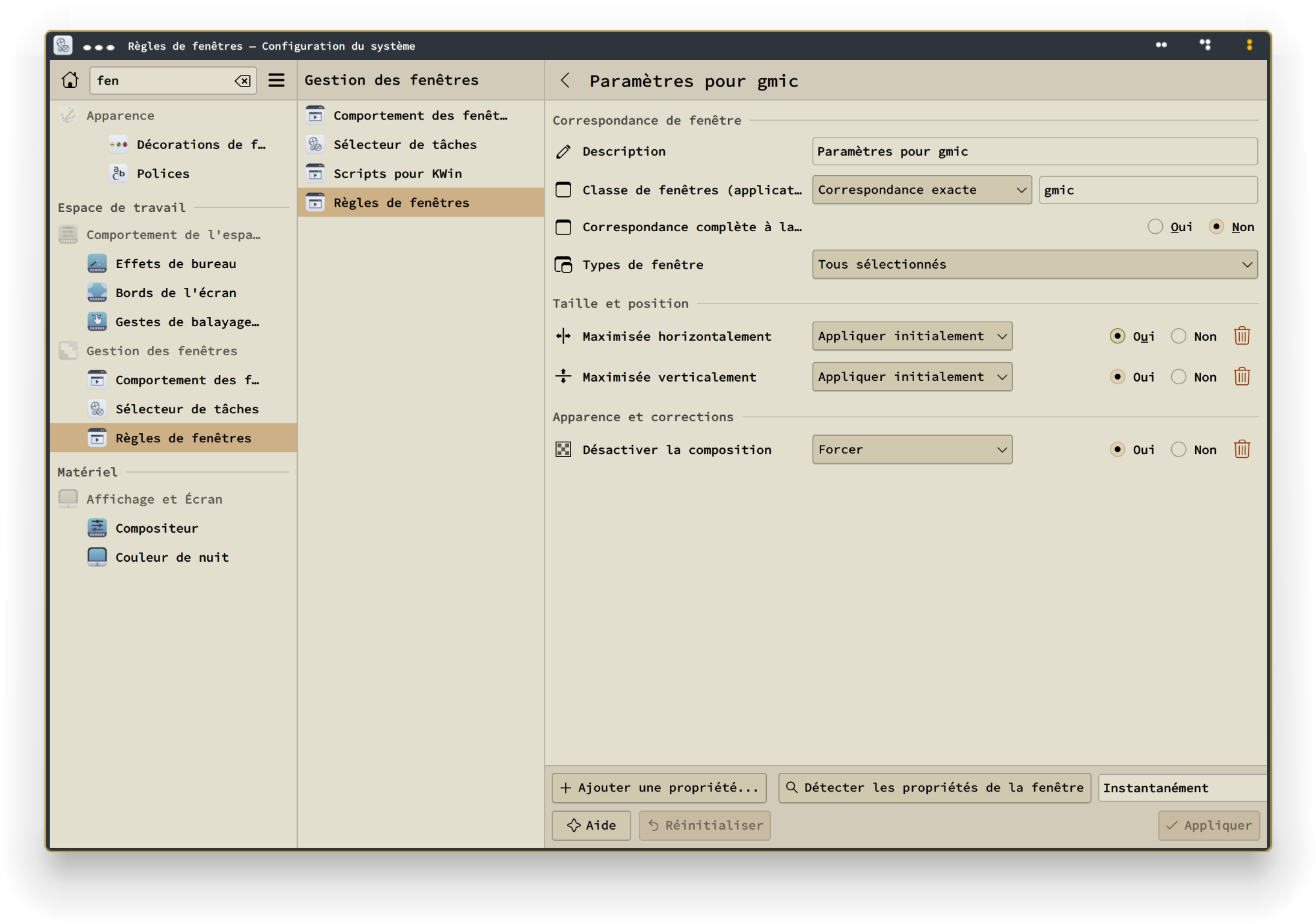
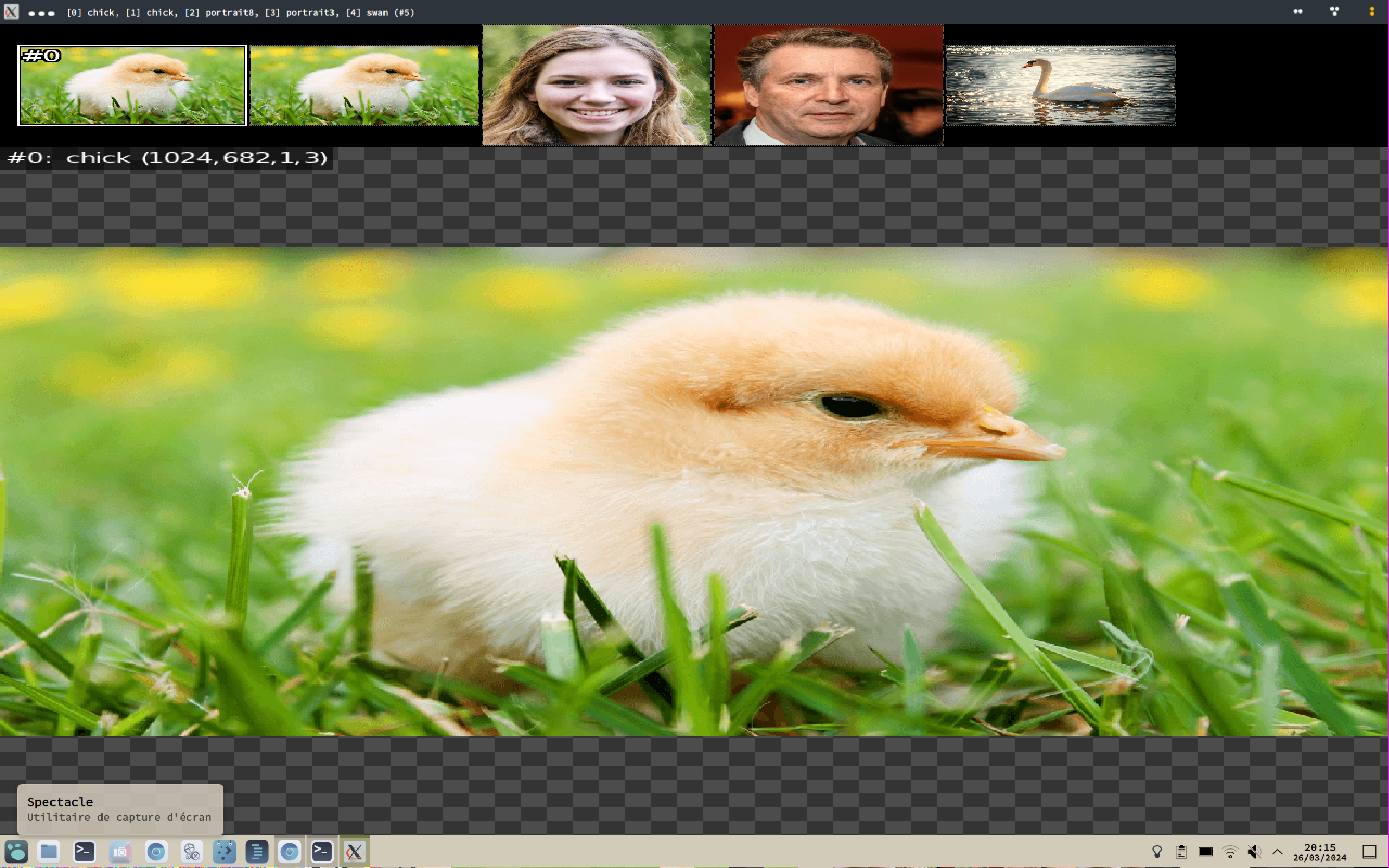
But anyway i used Kwin/Plasma options to maximize all G’MIC windows, so it’s less of a problem, though images are stretched when there is more than one (or so it seems) :
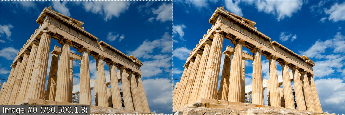
@SlavaCat118 On Linux, i used run and replaced the quotes with { } and it worked.
Made it +add too. gmic run 'sp +add {80*cos(80*(x/w-0.5)*(y/w-0.5)+c)} cut 0,255'
Don’t worry, it’s something I’ve been preparing for, since a long time.
I was almost 100% sure that the X-compatibility layer offered by Wayland will not behave exactly the same as with the original X11 library, and as CImg (the low-level library used by G’MIC) uses some quite low-level calls to X11 functions, troubles were (unfortunately) expected.
I don’t know about the alternatives though. Relying on a high-level library, as Qt or GTK, just to display images in windows is a bit overkill and add a zillion of useless dependencies. I’d like to stick with a low-level approach.
I’ve started reading the Wayland/Weston documentation, and it’s … hum… far from being done. Finding documented sample codes to display a simple image in a window is already a bit hard to find. But, at least, I think that it could be technically possible to add a Wayland binding for CImgDisplay. So maybe in the future (but damn, it seems so uninteresting to code…) ?
You have to keep in mind that the examples in the G’MIC command documentation are written in the G’MIC scripting language. In that language, you need some special characters such as ', {, } and so on…
But if you call G’MIC from a shell (e.g. bash or sh), these special characters are also used by the shell itself, and they are used before the call to G’MIC is done.
So, depending on the shell you use, it’s not unusual to have to quote or backslash those characters so that they can be indeed passed to the G’MIC interpreter.
In your example, with a bash shell, you’ll have to transform the example syntax a little bit, and write it as:
Yes, I’ve been forced to put the add argument between double quotes, so that the ', ( and ) characters are passed to the G’MIC interpreter as it. If you are using another shell, you’ll have to do something else (e.g. Powershell). That’s why we cannot put directly the bash-modified commands in the documentation.
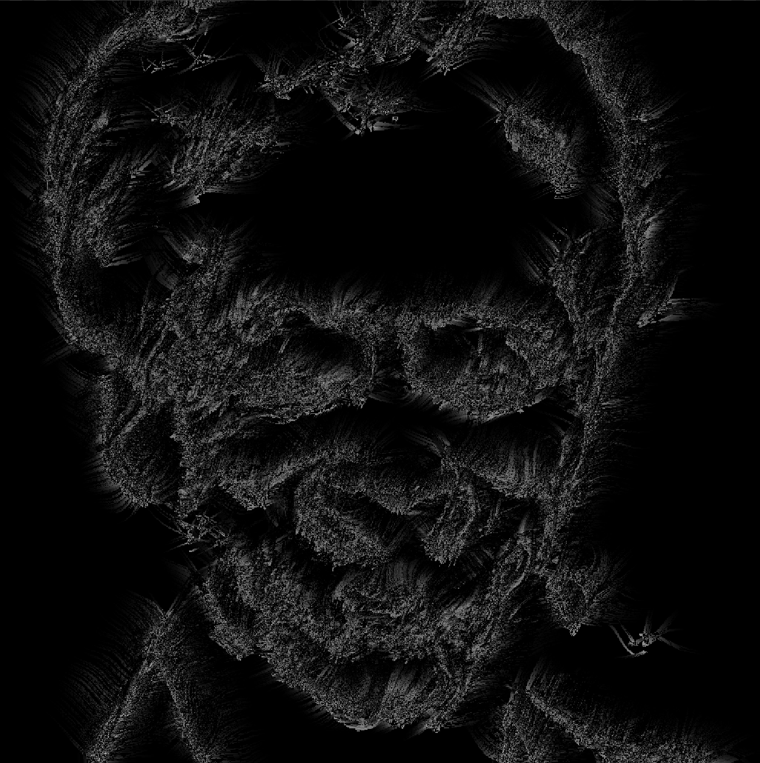
Then how do you make it “behave” like it should using run to avoid the backslash nightmare? It didn’t throw an error when I added { }, but it didn’t look like anything it should. Probably because it sent everything to the math parser and it is a totally different result?
Just see it as a test of endurance
I wonder, what does Image magick use to display images?
It works for me but always opens windows maximized.
(Or python since it seems it’s always there on linux?)
But maybe that’s too much, i don’t know.
But guys, do you know i’m still struggling with the real basic things of G’MIC?
Like this: 1500,700,1,3,[103,2,1]*y/(h-1) 100,100,1,3,"lerp([ 32,128,99 ],[ 200,0,16 ],y/(h-1))"
These create a gradient from one color to another, alright?
How do i add a third color?
And, how do i create a 1x3 image and give each pixel different RGB values?
i’ve seen this a lot : 1,3,1,3,'128,50,80'
but can’t do it for RGB triplets.
I think i’ve asked this before, but i can’t remember or find the answer.
When i do : (50;0;0^50;25;0^100;100;0)
Colors are wrong ; 50,0,0 becomes 50,50,100, etc.
Puzzling.
I’ve read this too :
(v1,v2,…)[xN]: Insert one or N new images from specified prescribed values. Value separator inside parentheses can be , (column separator), ; (row separator), / (slice separator) or ^ (channel separator). For instance, expression (1,2,3;4,5,6;7,8,9) creates a 3x3 matrix (scalar image), with values running from 1 to 9.
(‘string’[:delimiter])[xN]: Insert one or N new images from specified string, by filling the images with the character codes composing the string. When specified, delimiter tells about the main orientation of the image. Delimiter can be x (eq. to , which is the default), y (eq. to ;), z (eq. to /) or c (eq. to ^). When specified delimiter is , ;, / or ^, the expression is actually equivalent to ({‘string’[:delimiter]})[xN] (see section Substitution Rules for more information on the syntax).
At some point in time, try to absorb Input - 4. Prescribed Values if you have not already done so. This section covers inputting an image by way of a stream of numeric values.
Various non-numeric delimiters partition streams into column (,), row (;), slice (/) and channel (^) regions.
In this stream that you have written:
(50;0;0^50;25;0^100;100;0)
It probably is not obvious, but the absence of delimiters indicates as much about the organization of an image as their presence. There are no slashes or commas. So, at the outset, the image has at most one column and at most one slice. For if were otherwise, the presence of commas would delimit the stream into two or more columns, and the presence of slashes would delimit the stream into two or more slices.
Semicolons and carets are present, so the image is delimited into more than one row; rows are what semicolons delimit; and more than one channel; channels are what carets delimit. Taking into account the presence and absence of delimiters, this particular stream first fills row 0, 1, and 2 of column 0 (and there can only be one column). As these data precede the first caret, the flow necessarily is into channel 0 (we think of this channel as “red”; G’MIC could not care less). That first caret delimits channel 0 from channel 1; data following it flows into row 0, 1, and 2 of channel 1 (“green”). The second and final caret separates channel 1 from channel 2; data following it flows into row 0, 1 and 2 of channel 2 ("blue). This is how a stream flows into a 1,3,1,3 image. Homework: how would the flow go if all of the semicolons change to commas (Hint: since there are no semicolons, the flow would go into at most one row, but more than one columns)?
The color of the pixel in row 0 necessarily must be [50,50,100] because these three values are each the first items in each of the three channel blocks. and these first items successively flow into channel 0 - the block before the first caret, channel 1 - the block before the second caret, and finally channel 2 - the trailing block. Similarly, the three values that are the second items in each of the three channel blocks compose [0,25,100], the pixel in row 1. What is the pixel in row 2 (Can it be any blacker)?
Make various small images and observe how G’MIC prints them out in the console log.
gosgood@lydia ~ $ gmic run 'v 2 (50;0;0^50;25;0^100;100;0)'
[gmic]./ Start G'MIC interpreter (v.3.3.6).
[gmic]./run/__run/ Set verbosity level to 2.
[gmic]./run/__run/ Input image at position 0, with values (50;0;0^50;25;0^100;100;0) (1 image 1x3x1x3).
[gmic]./ Display image [0] = '(50;0;0^50;25;0^100;100;0)'.
[0] = '(50;0;0^50;25;0^100;100;0)':
  size = (1,3,1,3) [36 b of float32].
  data = (50;0;0^50;25;0^100;100;0).
  min = 0, max = 100, mean = 36.1111, std = 41.6667, coords_min = (0,1,0,0), coords_max = (0,0,0,2).
Ah thanks, i’ve been looking for this page for hours today…
Couldn’t find the link, all input links i found in the tutorials point to the reference page, which is less detailed. I knew this page existed, seen it last year lol. Could you tell me which page has the link? It’s hidden too well.
Anyway, i’ve finally noticed how the values were ordered in between the (), wasn’t sure if it was supposed to be this way, or if i did it wrong ( without your link, hard to figure this out). I’m used to write RGB colors as 255,0,0 for red, etc. , so you can guess how it can confuse me to split colors like you described.
In the end i wrote it this way for the “forest” gradient:
    (2;2;2;2;0\
    ^0;0;1;2;0\
    ^0;0;0;2;0)
More readability for me this way, i don’t have to “jump” over 2 values to guess a color.
I had to use very dark colors though, since with all the effects it would quickly become very bright.
3,1,1,3. I wanted a vertical image though, hence the use of ;
But i will allow a gradient along x axis too.
0,0,0. I wish it could be “more blacker” but anyway no screen could display it.