As I may have said in another thread, it is a combination of techniques. The newest iterations use machine learning as well. In general, they tweak the formula once in a while.
The reason that I bring this up is because post Version 2 (2010), the default processing is quite developed, even when sliders are at neutral.
Although clarity is probably a completely different beast in version 2 in comparison to 5, it would be great if you could provide version 2 clarity samples.
I think, of course, I do not have the code, that adobe uses an “EPD” (edge preserving decomposition).
You can see this effect, in the “blue horse” image and also (less) in the Venezia image.
With Rawtherapee you have now several ways to perform a function “clarity”…I don’t speak to “copy” Adobe, which for me does not make much sense, every software has its algorithms, its process.
Branch “wavelenh” - function “Clarity” - by using Residual image…and others effetcs
Branc “newlocallab”, several “local” tools, combining with “scope”, transition, etc…that can be used alone or in combination
CBDL - in fact it’s simplify wavelet (Harr), with Clarity
Tone-mapping (edge prererving decomposition)
Local contrast
Retinex - which is using an algo close to “local contrast” but more complex and for much larger radius values
Inspired by the clarity version of the blue horse image, I have started experimenting with “adaptive contrast stretching” techniques, and the result are rather promising:
I have always had trouble with the bright areas myself when developing techniques. ATM, I am just masking them out and / or treating them separately. In images where there is a clear separation between the light and dark, it is relatively simple as long as you threshold properly. Simple doesn’t always mean easy though.
Disclaimer: this is by no means a sort of reverse engineering of the Clarity tool, it is instead a mere comparison with well-known image processing algorithms
Today I made another interesting observation regarding the way clarity works.
In fact, the basic algorithm seems to be quite simple, and well known. It can be summarised like this:
R = L/L_{mean}
L_{out} = L * R
RGB_{out} = RGB * R
That is, the input RGB values are scaled by the ratio of the RGB luminance over a local mean value.
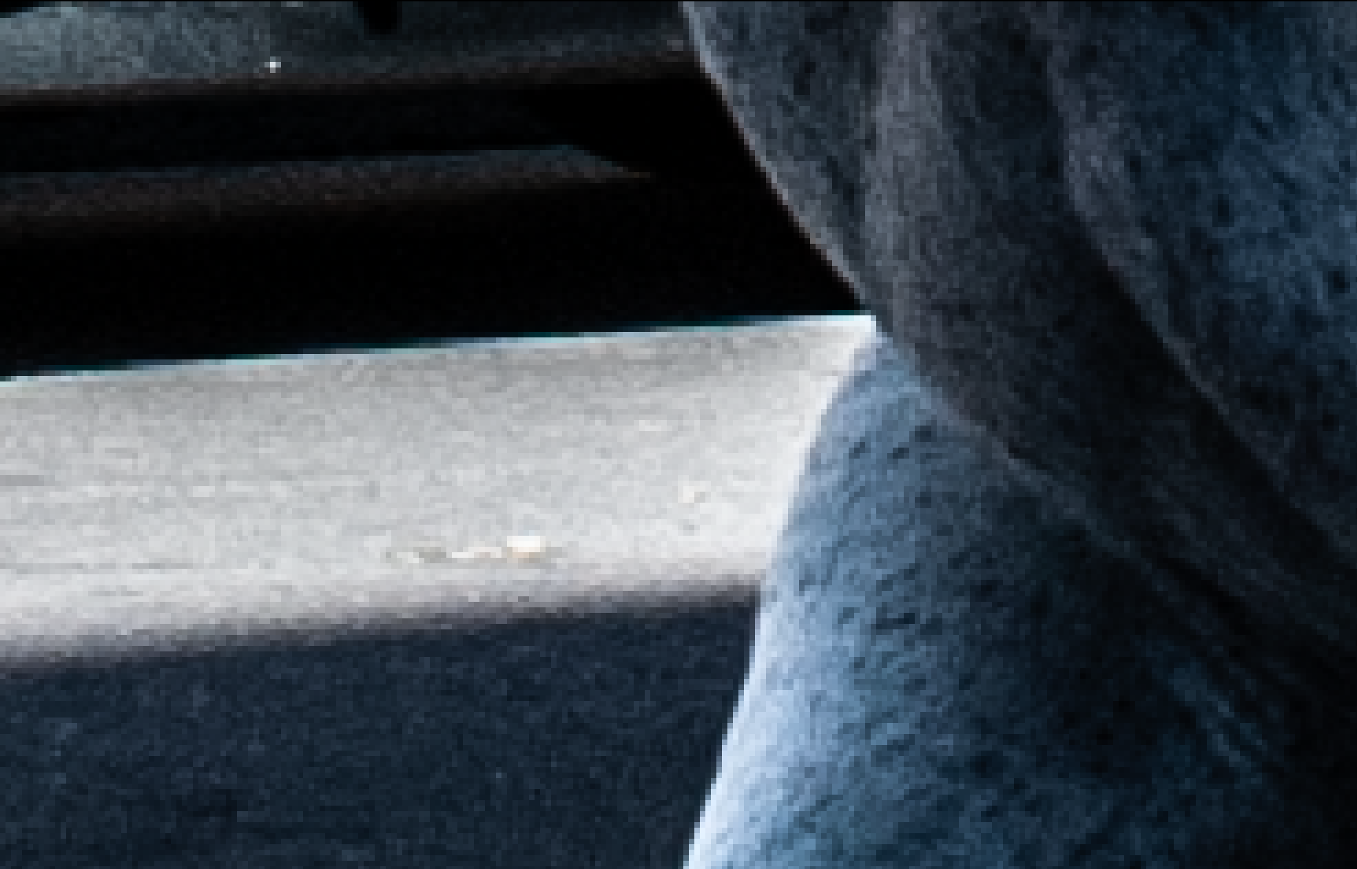
To demonstrate this, I have divided the Clarity=0 blue horse image by a constant value, and used the formula above to create an equivalent of the clarity output. Here are two crops, corresponding to two different choices for L_{mean}, one around 0.5 for the bright stone wall, and one around 0.05 for the dark doorway. Here are the results:
Of course, this is just the tip of the iceberg… the main challenge is of course to implement a good edge-preserving averaging method. I will see what I can obtain with the incremental guided filter I am using for the shadows/highlights tool.
Some more investigations and observations, based on the Clarity=100 blue horse image.
First of all, in the following I will make the hypothesis that clarity enhances the local contrast using the “ratio” formula I introduced here, and which can be re-written as
L_{out} = L^{2}/L_{mean}
If the above formula is valid (even approximatively), it is then possible to derive the L_{mean} image from the input and output:
L_{mean} = L^{2}/L_{out}
that is, take the clarity=0 image, multiply it by itself, and divide by the clarity=100 image.
I did the exercise, and this is what I obtained. I let you look in detail at the image and its properties…
I have been experimenting quite a lot with local contrast those days. The algorithm I am developing is still based on my “incremental guided filter” for the image smoothing, using the “ratio of values” approach I outlined above.
What I added on top of the basic algorithm is some code that protects highlights and dynamically adjusts the enhancement of the local contrast based on the tonality of the blurred image. Shortly speaking, in regions where the blurred image is bright the code emphasises more the dark details, and vice-versa in dark regions. Dark and light details are enhanced symmetrically around mid-tones.
Here is what I am obtaining with the house image (I need to post a full-res image because details here really matter):
I hope to be able to commit the code in PhF during this weekend. I can also explain the details of the algorithm is anyone is interested…
Please notice that this has nothing to do with LR’s clarity tool. In particular, it is clear that clarity introduces some “smart” local tone adjustment, using I guess a rather non-trivial logic. See for example the house image at clarity=100%, and how the bright areas at the bottom-left are darkened much more that the walls of the building on the right…
Once you have committed the code, please share your PFI in the post above so that we may play with the module and see how you have set up the pipe prior to its application. That way we can compare and contrast. And maybe a before image for those who don’t want to examine the PFI.
@heckflosse I think it is fine. Although the app in the latter half of the discussion is PhotoFlow, the discussion has been on the strategies. Perhaps, we could change the category to the more general Processing and then tag away the rest (ATM, RT, PhF and briefly G’MIC).
@Reptorian Are you suggesting that you have something in the works? I have already been using a bare bones version that I demonstrated above. Not the best example images but it worked in my latest PlayRaws. As with almost all of my commands, they never reach community.