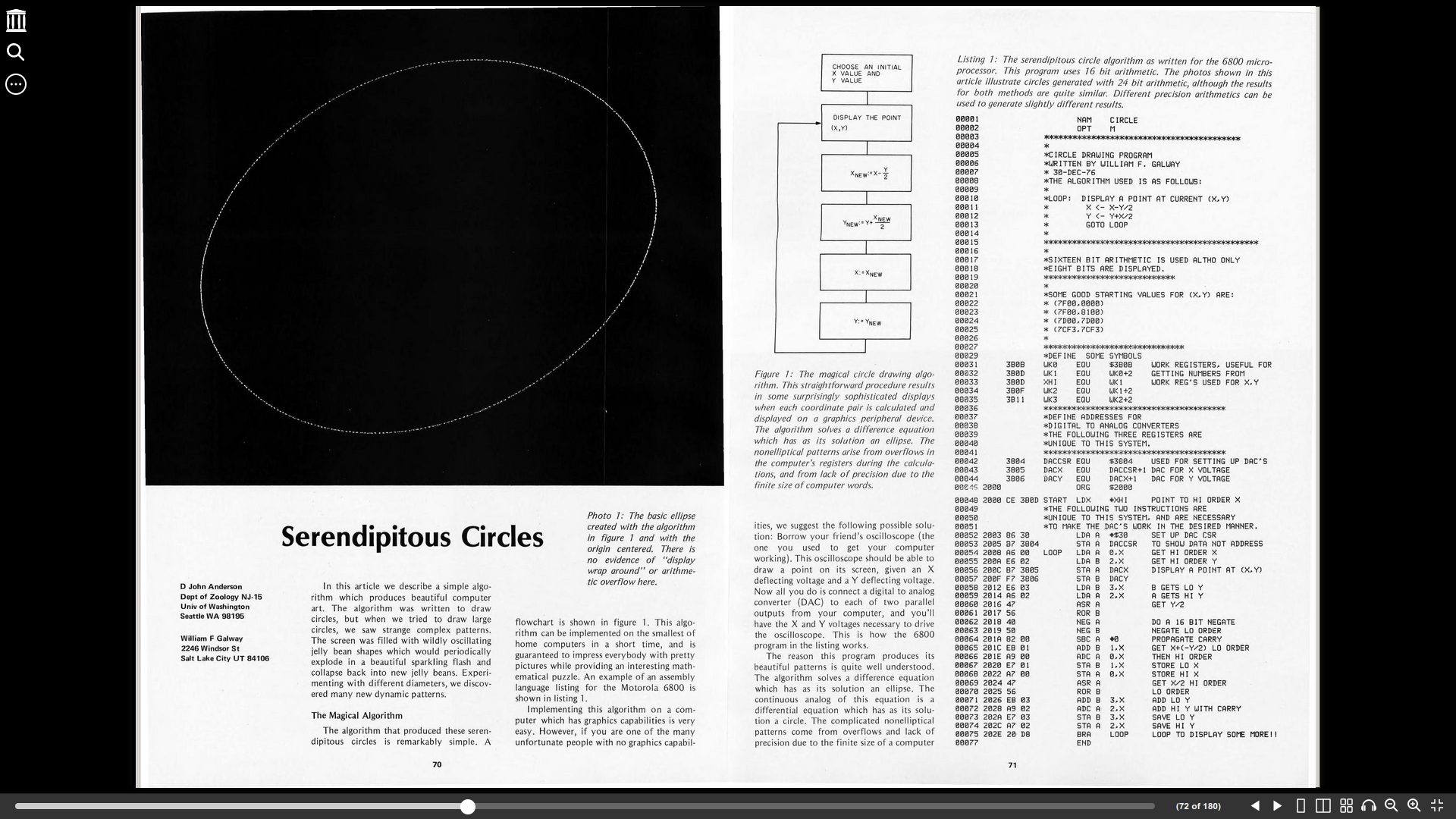
That code is not just old, but it’s 6800 assembly, and (like all assembly code) not easy to reverse-engineer. However, the algorithm is right there in figure 1 – you can implement that in any modern language. Let me know if you want me to take a shot at it.
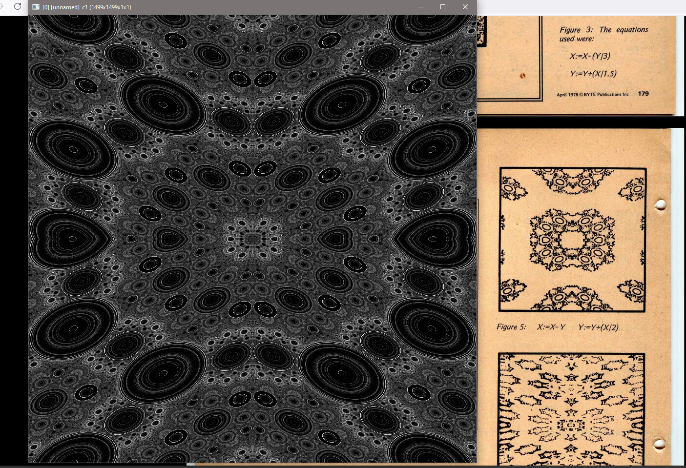
I’m not that good at G’MIC, so I’m trying with another language I’m more familiar with (Julia), but so far I’m not getting anything interesting. I wonder how much of the effect depends on the properties of analog displays (as described in the article).
How many iterations are you running, and what initial values?
num_of_points is used to define $1. I forgot to change $1 to num_of_points.
$1,1,1,1 means an array/image of size $1,1,1,1 (width,height,depth,color_array_size). i(#-1,x,y,z,c)++ means that I am incrementing image #-1 at point x,y,z,c by 1. Negative image indice means last n image.
So, in short, I added a image of size 5000,5000 before applying the command, and then resize the 5000x5000 image to 500x500 after applying the command.
I haven’t spent thought on it, likely all the changes caused by the limited register can be emulated with simple operations such as modulo and int. I have done 6800 asm a long time ago, but this shows how poor my memory is! What’s tricky for me to work out may not be for you
For everyone, who would like to run the code in an emulator, I’ve copied the code and fixed the obvious errors from the OCR:
00001                      NAM CIRCLE
00002                      OPT M
00003               ******************************************
00004               *
00005               *CIRCLE DRAWING PROGRAM
00006               *WRITTEN BY WILLIAM F. GALWAY
00007               * 3El-DEC-76
00008               *THE ALGORITHM USED IS AS FOLLOWS:
00009               *
00010               *LOOP: DISPLAY A POINT AT CURRENT (X,Y)
00011               *X <- X-Y/2
00012               *Y <- Y+X/2
00013               *GOTO LOOP
00014               *
00015               **********************************************
00016               *
00017               *SIXTEEN BIT ARITHMETIC IS USED ALTHO ONLY
00018               *EIGHT BITS ARE DISPLAYED.
00019               ****************************
00020               *
00021               *SOME GOOD STARTING VALUES FOR (X.Y) ARE:
00022               * (7FElEl,El000)
00023               * (7F0El,SI00)
00024               * (7D00,7D00)
00025               * (7CF3.(CF3)
00026               *
00027               *******************'***********
00029               *DEFINE SOME SYMBOLS
00031      3B0B     WK0    EQU $3B0B WORK REGISTERS, USEFUL FOR
00032      380D     WKI    EQU WK0+2 GETTING NUM8ERS FROM
00033      3B0D     XHI    EQU WK I WORK REG'S USED FOR X,Y
00034      3B0F     WK2    EQU WKI+2
00035      3811     WK3    EQU WK2+2
00036               ***************************************
00037               *DEFINE ADDRESSES FOR
00038               *DIGITAL TO ANALOG CONVERTERS
00039               *THE FOLLOWING THREE REGISTERS ARE
00040               *UNIQUE TO THIS SYSTEM.
00041               ***************************************
00042      3804     DACCSR EQU $3804    USED FOR SETTING UP DAC'S
00043      3805     DACX   EQU DACCSR+1 DAC FOR X VOLTAGE
00044      3806     DACY   EQU DACX+1   DAC FOR Y VOLTAGE
00045 2000                 ORG $2000
00048 2000 CE 380D  START  LDX #XHI POINT TO HI ORDER X
00049               *THE FOLLOWING TWO INSTRUCTIONS ARE
00050               *UNIQUE TO THIS SYSTEM, AND ARE NECESSARY
00051               *TO MAKE THE DAC'S WORK IN THE DESIRED MANNER.
00052 2003 B6 30         LDA A #$30        SET UP DAC CSR
00053 2005 B7 3804       STA A             DACCSR TO SHOW DATA NOT ADDRESS
00054 2008 A6 00    LOOP LDA A 0,X         GET HI ORDER X
00055 200A E6 02         LDA B 2,X         GET HI ORDER Y
00056 200C B7 3805       STA A DACX        DISPLAY A POINT AT (X.Y)
00057 200F F7 3806       STA B DACY
00058 2012 E6 03         LDA B 3,X         B GETS LO Y
00059 2014 A6 02         LDA A 2,X         A GETS HI Y
00060 2016 47            ASR A             GET Y/2
00061 20l7 56            ROR B
00062 2018 40            NEG A             DO A 16 BIT NEGATE
00063 2019 50            NEG B             NEGATE LO ORDER
00064 201A 82 00         SBC A #0          PROPAGATE CARRY
00065 201C EB 01         ADD B 1,X         GET X+(-Y/2) LO ORDER
00066 201E A9 00         ADC A 0,X         THEN HI ORDER
00067 2020 E7 01         STA B 1.X         STORE LO X
00068 2022 A7 00         STA A 0,X         STORE HI X
00069 2024 47            ASR A             GET X/2 HI ORDER
00070 2025 56            ROR B             LO ORDER
00071 2026 EB 03         ADD B 3,X         ADD LO Y
00072 2028 A9 02         ADC A 2,X         ADD HI Y WITH CARRY
00073 202A E7 03         STA B 3,X         SAVE LO Y
00074 202C A7 02         STA A 2,X         SAVE HI Y
00075 202E 20 D8         BRA   LOOP        LOOP TO DISPLAY SOME MOREll
00077                    END