So when it comes to photography the workflow discussed will likely be most useful for something like a company producing an ad campaign based on the work of multiple photographers and locations. Or for the very successful photographers who have a lot of people working for them. Perhaps photographers producing books where the work need to look very consistent despite being shot at very different locations?
I do have series of photographs of the same subject (buildings) taken with years and gears between them. Would aces theoretically help making them more consistent?
Sure, so explain to me what 300$ colorimeters do when they sit on my screen if it’s not measuring an output error, later baked into a correction transform…
So the colorspace is the standard x vector (or matrice), the native behavior is the response transfer function of the screen y, another vector (or matrice), you go from x to y by multiplicating x by the matrix M of a linear map, which you need to solve for (x, y), (maybe followed by a non-linear transfer function) and the emulation is M^(-1) the inverse transform of the hopefully inversible M (maybe preceeded by the inverse non-linear transfer function). That’s exactly what I said, except I describe it in terms of general maths and physics, and you describe it in terms of technical-end/computer-science implementation.
That’s why I hate everything about ICC and color management : simple scientific things get buried inside piles of slang and people lose the goal of the linear algebra they perform in the sea of files formats and profiles standards. For God sake, the Delta E 76 is just an euclidian (L2) vector norm, an RGB space is a non-orthogonal vector space, a color profile is just a coordinates change between 2 non-orthogonal vector bases, and a calibration is a matrix inversion. That’s 2nd year maths classes in every applied sciences university…
No, this workflow is useful for everyone since you work in a space where multiplication means multiplication, addition means addition, with no non-linear unpredictable thing happening, and where pixel pushing is straight-forward and safe because the 3 RGB channels increase or decrease all by the same amount, preserving the original color. ACES workflow ensures the masters will survive all future output changes, but also ensure one retouch setting has only one effect on the image. Plus, they define standard image adjustements so you can transfer the settings from one soft to another without having to use anything but the original master (and not an intermediate exported file).
Get out of that nonsense = think of it as basic matrices products, because right now we are all trapped into the ICC overhead/dogma to describe really simple maths. It’s a typical case where the theory is actually much simpler than the technicalities, and the initial goal to build tools to make things easier backfired.
The instrument has no reference to compute an output error. It just measures color. That’s why you need two profiles to create a device to device space transformation/calibration transform.
Even a so called “display calibration” process has two “profiles”, one being the measurement values from the instrument, and the second being the target response that is desired from the display (which typically is computed by the calibration software, based on the users specifications, and measurements such as white point, black point etc.)
Except you have grossly simplified what’s going on, and made it incomprehensible to most people, by speaking in very abstract, mathematical terms. And worse, you have ignored the key point of color management, the intermediate “common language” that allows all this to happen, namely device independent color measurement.
It’s not simple, and it’s not linear algebra. There are specific terms that have meaning, in order to convey the logic of what’s going on. Yes the guts of the implementation may be specified in terms of physics and mathematics, but attempting to convey the over-arching concepts and logic in such abstract mathematical terms would simply be bamboozling to most people.
Yep. Except that you have overlooked that is euclidean distance in a colorspace specifically designed to make it the euclidean distance.
And now try describing what Delta E 94 and Delta E 2000 are in “simple” physics and mathematical terms.
I think you’ll find that it’s an orthogonal vector space, by definition. It’s only non-orthogonal when viewed in some other colorspace.
Yes but no. That’s just machinery, and often the machinery is not so simple. Conceptually a profile is the correspondence between device dependent and device independent space. That’s the key point that you seem to have missed.
Except it’s not a matrix, and the the overall process of creating a calibration or transform involves linking two profiles.
Your overall attitude seems to be “Color is simple because I understand some physics and mathematics”. You are dead wrong. It is based on physics, physiology, mathematics and computing. They all interact to make for and interesting and deep topic, one that certainly justifies its own terminology and a great deal of study.
The full ACES workflow might be useful in such a scenario (do note that the full ACES workflow does includes ways to communicate these color decisions which is not necessary for an individual photographer)
Splitting things into an overall look and feel, and individual edits can indeed help here.
But this does not require a full ACES workflow, any workflow that is non-destructive, works in a scene referred workspace and can be encoded using OCIO will do this ass well. Sure ACES specifies some additional metadata but these are strictly speaking not necessary to make the above work (do note that OCIO was created before ACES was developed!)
Also on top of that ACES can and does use digital intermediates just look at this Official example workflow (found at the ACES primer linked above) and then note especially the output from compositing to DI grade which is in ACES2065-4 EXR files on top of that input to compositing might be either in that format or camera original, so depending on the choices made the compositing department might never see the camera originals at all!
As an example the current OCIO configs recommended for use with blender (either the default or filmic) are not fully compatible with an ACES workflow (they can output in ACES2065-4 EXR so the outputs can be used but that is about it) but still will have most of the advantages described above if used in a suitable workflow (which won’t be ACES).
Sure, because hiding the formal logic deep inside a CMS is the best way to… stay a color guru while nobody else has a clue of what happens ? Maths are the language of logic, to avoid a few lines of equations, you need dozens of pages of specs for dummies (that’s what the ICC specs are), so at the end you just obfuscate things ever more. (And I don’t care about most people: most developers have made Linux a color-management nightmare).
The PCS/common language is completely optional and doesn’t change what I have said: your x vector might be a PCS or another device-dependant RGB, the math remain.
This is straight out from the ICC v4 spec, that’s exactly what I have described in maths terms, and I fail to see how any of this is more complicated than solving linear applications and measuring non-linear transfer functions. Once you remove all the slang and the overhead, it pretty much looks like any metrology I have done in the past years: calibration curves, eigenvalues, eigenvector, transfer matrices, LU descents, gaussian elimination… that’s it, your CMS is a very inefficient BLAS with text parsing features.
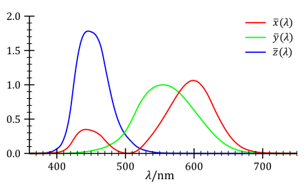
This is the spectral distribution of the 2° CIE observer:
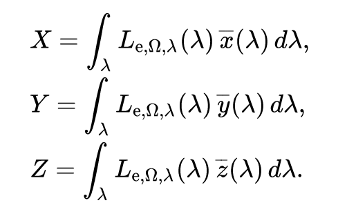
Given that the spectral coordinates are expressed in the XYZ vector space by the integrals of these distributions:
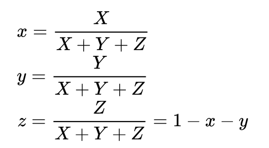
and given that these spectral distributions are non-uniform and overlapping, I’m pretty sure that there is no way to make the XYZ base vectors linearly-independant, which is one necessary condition to have an orthogonal vector base. It’s even clearer in xyY space:
z is explicitely a linear combination of x and y. No orthogonality here.
So, any RGB base defined by linear combination of the XYZ vectors is non-orthogonal as well. It’s my understanding that only Lab and similar luminance/chrominance-defined spaces are orthogonal. (Not to mention that the Grassman law upon which all of this is based is a gross simplification in itself, so ultimately there is no point in trying to do scene-referred work inside human-referred RGB spaces).
But I must admit that I don’t get how the CIE wizards come from a 2D spectral space (wavelength, intensity) to a 3D physiologic tristimulus space (3 cones response) XYZ space where suddenly Y is not the green cone response but the luminance.
You mean that psycho-sensorial BS to build perceptually uniform spaces that have no physical meaning anymore ? Funny enough, this topic is specifically about avoiding that, hence “scene-referred”. Also, if Lab was needed to have an euclidian norm, that confirms my point on RGB spaces being non orthogonal (non euclidian).
You really miss the point here. The ICC workflow is stream-lined display-referred. RGB spaces are defined from XYZ which are defined from the spectral transfer functions of average human cones. First of all, these RGB spaces are not where the photons live, they are fair approximations of the spectral world (wavelengths, intensities) viewed through human goggles. That the best we can do for now, but that will never be true scene-referred and that has been spotted in 3D rendering to cause color shifting problems (the most spectrally-accurate RGB is REC2020). The point of scene-referred is to work (as close as possible from) where photons live, for us photographers, it means having exact digital equivalent of darkroom operations and films emulations.
Then, the ICC workflow doesn’t define a safe working space to push pixels. In ICC, you go from display space to display space (maybe using PCS, aka XYZ or Lab, which are even worse to push pixels). Even if you put a RGB working buffer in-between, like Adobe RGB or whatever, the ICC conversions may pass trough Lab, which might or might not be safe to preserve scene-referred ratios (I have to ponder that) and anyway assumes you convert for the CIE 2° observer, whereas ACES don’t care about the observer and go from technical RGB to RGB without assumptions in-between: no intent, no clipping, no funny TRC.
In ACES, the whole PCS is the RGB pixel-pushing working space and everything is done from and to this space (model/view architecture). In ICC, the PCS has no graphic interest whatsoever, except being a non-linear perceptually uniform space for humans that feels awesome because coordinates are orthogonal and you can mess up with chroma and luma in completely separate ways.
ICC = printer, ICC = screen with caution, because GTK/Gnome/Xorg/Nvidia stack does undocumented things with color profiles and you have no clue to guess (at some point, it feels safer to live in whatever sRGB your screen was designed for), but ICC in input is from another era.
It is not true that in ICC you go “from display space to display space”. This is something I heard quite often, that ICC is “only for display-referred editing”, but there is no proof of that. In fact, with ICC you can define and use linear working colorspaces for scene-referred editing. If you choose linear ACES, then this working colorspace has the exact same mathematical meaning as the one defined in the ACES specs.
It is up to the input transforms to make sure that the pixel data that land in the linear working colorspace are truly scene-referred, but this problem is not ICC-specific. ACES introduces IDTs for this, ICC has input profiles, but conceptually the two things are equivalent.
Moreover, the PCS has no practical implication in the pixel manipulations, because it is an “hidden” space that you never use. It is there to make the ICC profiles independent from each other. Imagine you want to print a scanned image. For this you need an input profile for the scanner, and an output profile for the printer. You could build a direct transform from scanner to printer, but you would need to re-compute it whenever you change one of the two. ICC profiles provide instead transforms from input to PCS, and from PCS to output. If you change your printer, you only need to create a new PCS → output transform for it.
However, the direct transform scanner -> printer and the ICC transform scanner -> PCS -> printer will give the same result, because the PCS is just an intermediate step that is invertible.
Event if the PCS is not linear, this doesn’t matter either, because the non-linearity is analytically invertible.
You might say that this is an un-necessary complication, but it is in fact needed to give flexibility to the mechanism.
ACES introduces IDTs from some input devices to ACES, and then further transforms from ACES to ACEScc/ACEScct/ACEScg. You might therefore consider ACES as a PCS if you want to go from camera to ACEScc. What’s wrong with this?
This thread has somehow diverged from my initial idea, and has become mostly a debate on wether ICC specs are appropriate or not for photographic editing.
My personal summary of the debate is that ICC specs, and the whole ICC machinery, is perfectly adequate for scene-referred editing, provided that appropriate input profiles are available and a suitable linear working colorspace is used for the scene-referred pixel manipulations.
What I am still wondering, and this brings me back to the initial questions, is wether ICC profiles are also appropriate and easy to use when it comes to preparing the final image for different display technologies, including the more and more common “HDR displays”.
I am pretty sure that an image should be prepared differently when they are viewed on a SDR display with 100 nits of brightness, or and HDR display that is 10x brighter.
The ACES standard claims to be able to provide a set of transforms that guarantee a consistent rendering of the same edited “master” on different display types (see chapter three of the ACES primer, starting at page 18). I am seriously asking myself if the digital photography workflow should go down the same path… and I tend to say “yes”.
After all, we create static images instead of moving ones, but what’s really the difference?
The first step is probably to try integrating OCIO in our software, and use it to handle the final stage of the editing process - from the working colorspace to the output one, be it the display, or a file to be viewed or printed (in each case, the output transform will be different I suppose). Inside OCIO, one can decide to adhere to the ACES recommandations, or explore alternative implementations.
I propose to focus on this aspects for the rest of the thread, and eventually move the “ICC is good/bad” debate to a new one…
Sure, we can break it out to a new topic to continue the discussion there - I have to admit to not being familiar enough with the material to know what to break out - could you flag all the posts in this topic that you think should be in a new thread? (or @Carmelo_DrRaw can also do it I think?)
Maybe these posts? @Carmelo_DrRaw - any deletions/additions? I’ve gone through the list twice and found some clearly wrong post numbers and removed them, but a second set of eyes would be good.
I also considered adding the discussion of “linear” wrt to ICC profiles just prior to post 13, but parsing out some confusions between the different meanings of “linear” and the value of linear gamma editing seems germane to the flow of the discussion.
13
14
15
part or maybe all of 16
42
43
44
45
46
47
48
49
51
82
83
84
86
87
88
89
90
93
95
98
102
103
105
106
part of 107
I’d advise just starting over. This thread in its entirety constitutes a conversation, each post has context with the others that cannot be teased apart without losing meaning.
Normally I’d agree with you. But the long discussion between @gwgill and @aurelienpierre - in which @gwgill is so very patiently trying to point out where @aurelienpierre’s understanding of how ICC profile color management actually works is fundamentally flawed - with other people occasionally chiming in to help - this is a discussion that is quite apart from the main topics that are being discussed.
For example, the posts by @dutch_wolf, @nosle, @Tobias, etc starting with post 75 are about possibly setting up a test implementation of an actual ACES workflow possibly using Blender or Krita or Natron, plus a discussion of what parts of the ACES workflow (however it might be implemented) could be useful for photographers with various goals.
But this handful of totally relevant posts is interrupted by 15 very long posts that mostly or entirely address or consist of @aurelienpierre’s complaints about and misunderstandings of ICC.
I see over in one of the Natron threads something about 2D and 3D for Natron and Blender. I think maybe Natron is easier for complete newbies to start using, compared to Blender? This is just a guess! As the Natron people are on this forum, could they help with setting up whatever is needed to implement enough of an ACES workflow (edited - previously said “transform”) so that people could see what it’s like to use?
Blender would actually a bit easier (after some setup but that could be stored in a .blend file) since its output is properly color-managed for Natron it needs an extra node to pick up the OCIO config before the view node. Do note I am talking about the compositing here (the renderer of Blender still uses Rec.709 primaries)
Going to see if I can do anything with a default ACES config later this evening.
Addendum/Edit
Going to ignore aurelien’s previous reply to me since he seems to have completely misread what I was talking about namely a photographic centered alternative (or actually any alternative) to ACES not anything related to ICC
WIll try to answer this to my best understanding do note I am not an expert at this, so take these answers with a pinch of salt
2D is 2 dimension think you’re typical image
3D can mean a couple of different things from a 3D scene created in blender (or other 3D editing SW) to a 3D lut (used to do color transform effectively tells how an RGB triplet get converted to an R’G’B’ triplet), the first meaning of 3D is not very relevant (the 3D workspace people where asking for in Natron is to make it easier to composite a render of a 3D scene with other elements)
At it barest it is creating a image from a set of metadata, in this particular instances it means turning a 3D scene into a 2D image (view from a virtual camera) or rendering out a composite to a final image
Compositing is generally turning multiple 2D images into a single output (theoretically you could have 3D compositing of scenes but that hasn’t been done) a 3D scene first needs to be rendered out before it can be composited (although for complex operations it can be rendered out in layers)
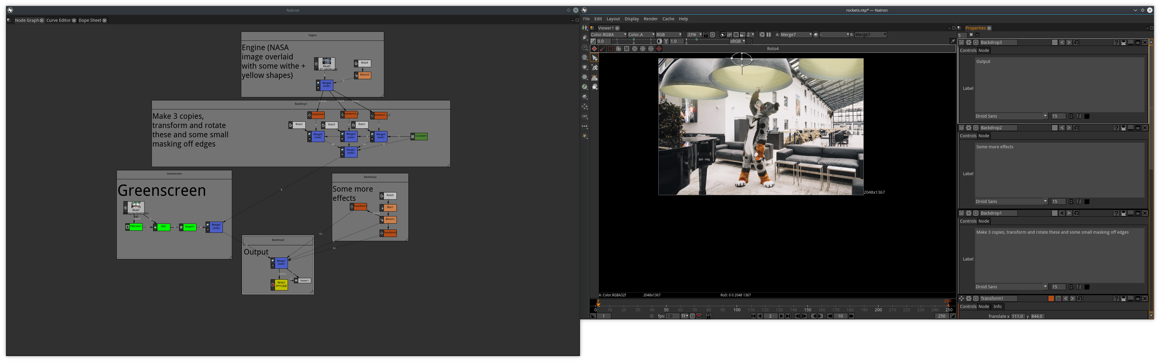
Yes although you do have the blends modes available they are found in a mix node where 2 (or more!) images are “mixed” together, this is mostly useful to not duplicate any inputs.
Sample below (EDIT: This is a sample of node based editing NOT ACES or scene referred)
The primaries are Rec.2020 primaries. If you have an equation for the TRC and you put that into a spreadsheet to generate however many points you want for the TRC, I can make you an ICC profile - it’s super easy to do using iccToXML and iccFromXml.
If you have a link to the documentation that provides the equation that you want for the TRC I might be able to set up the spreadsheet myself.
I’m guessing you want at least 4096 points for the TRC. But more are possible.
Edit: From the point of view of ICC profiles, we speak of TRCs. In the realm of building and calibrating electronic display devices to various standards, the term “EOTF” is used, such as the EOTF specified in BT.1886:
“EOTF” specifies the desired calibration state of the display device. How well an actual display device conforms to the intended calibration specification is something that must be measured and perhaps periodically corrected by recalibration. In studio environments I’m assuming there is staff that ensures that the display devices all actually do conform to their nominal specifications.
This term “EOTF” is not directly interchangeable with the term “ICC profile TRC”. The first is a specification that includes a transfer function that a given display should conform to. The second describes the actually measured transfer function for use in an ICC profile color-managed application. If one assumes a given display conforms to the spec, then one can make an ICC profile that describes the display. This might be splitting hairs, but I think it’s an important distinction.
In an OCIO workflow, there are chains of transforms, the last one of which is a LUT that maps the channel values of the image to the corresponding RGB signals that are sent to the display. Making this last LUT requires knowing the actual state of calibration of the display and also requires knowing the RGB color space of the image that’s being sent to the screen.
In an ICC profile workflow, the image is in a user-chosen ICC RGB working space and the user has supplied a monitor profile. ICC profile color management takes the image RGB channel values to the PCS (“profile connection space”, either XYZ or LAB), and then from PCS to the monitor profile color space, and the resulting RGB intensities are sent to the display.
As an aside, in GIMP and I think in darktable, when the source and destination profiles are both RGB matrix profiles, the conversion from RGB(image) to XYZ to RGB(monitor) is just done using matrix math, and the resulting RGB intensities are sent to the screen without actually invoking LCMS.
@gwgill, anyone who knows, please correct any errors in what I just posted!