Hi! Found an older lightroom edit from a trip, that I tried to reedit in Darktable 5.4. I found some problems in parts of the reconstructed sky - hard edges that I could not eliminate
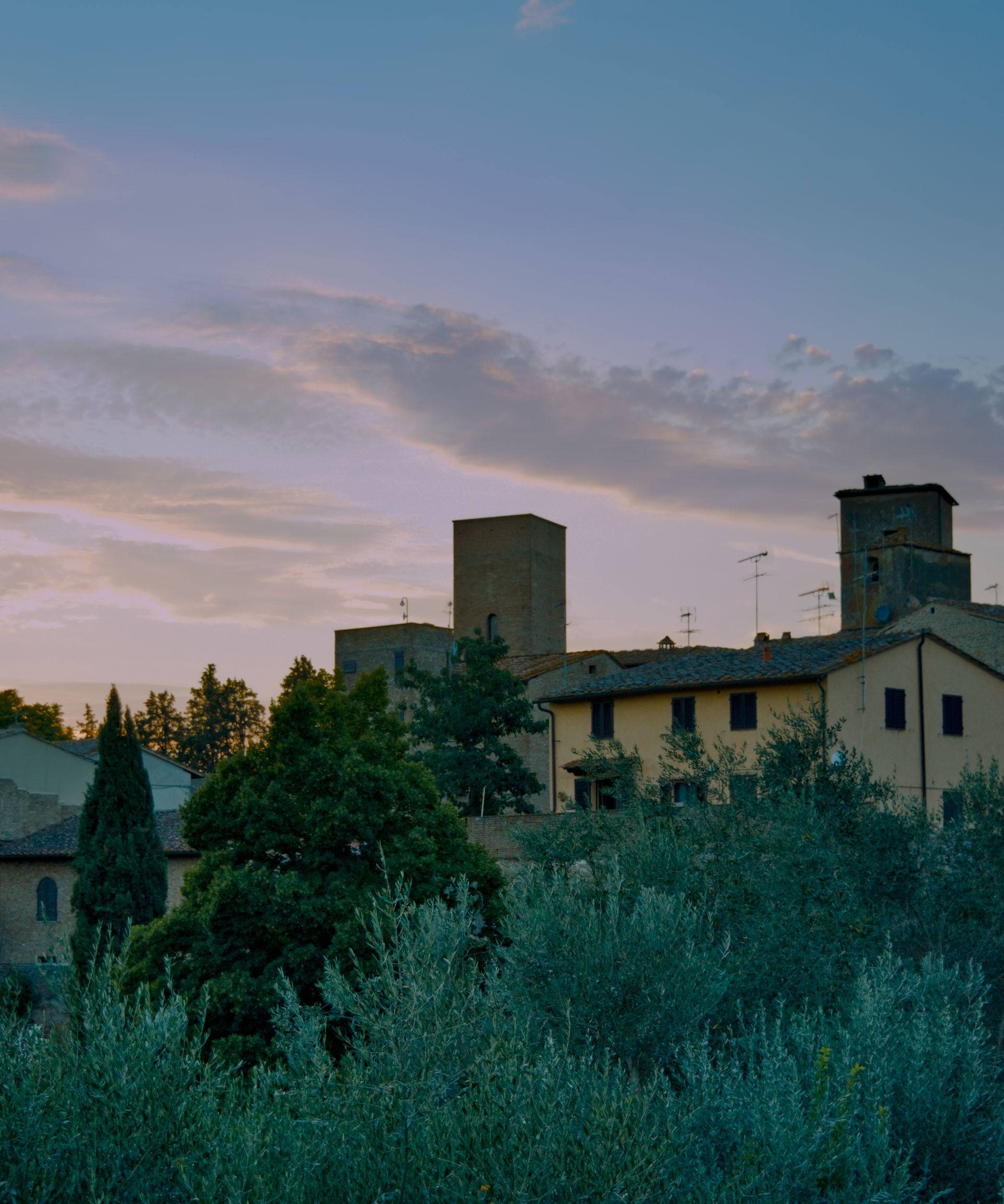
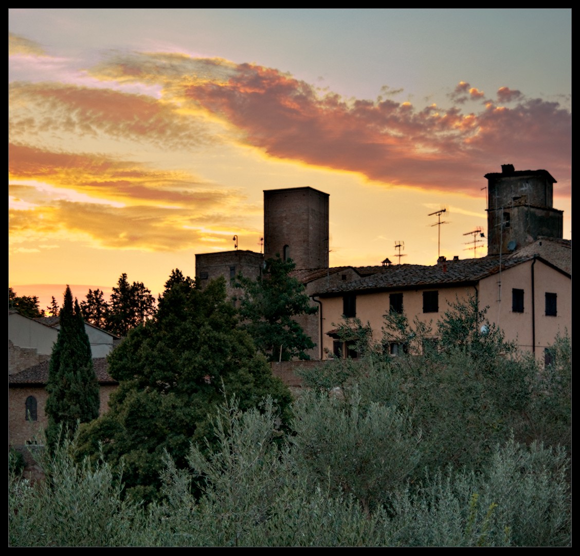
Here is the lightroom version without the artifacts. Something similar can be achieved with filmic´s highlight reconstruction but not with sigmoid or agx.
There were some challenging issues with the clipped highlights. I opened the image in both LR and DT. The issues were apparent in both programs. However, I will confess that LR facilitated the easier edit of this image.
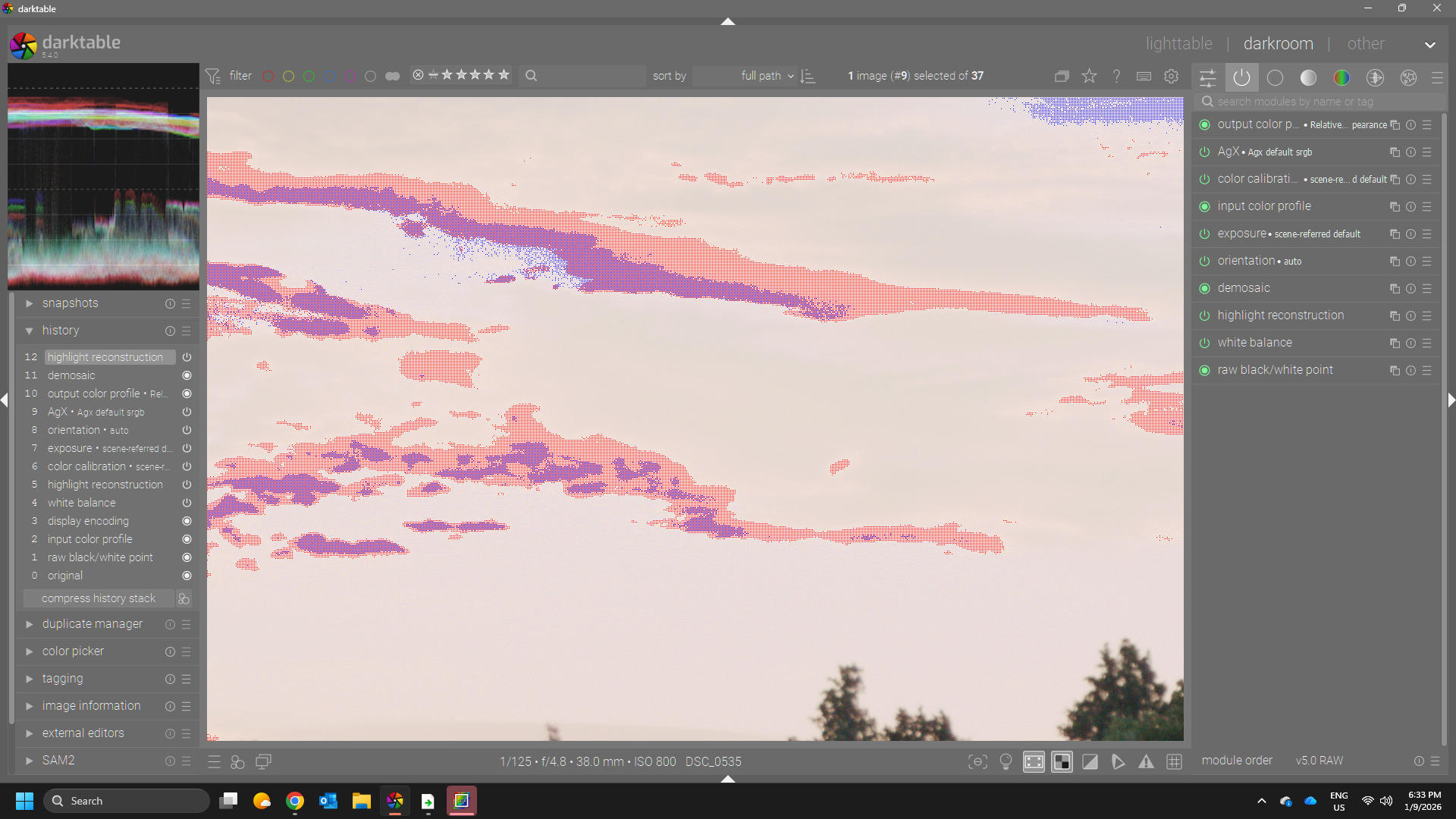
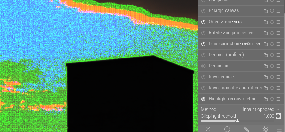
In DT I had to adjust the threshold for the highlight reconstruction module to reduce magenta highlights.
Here is my edit in DT 5.4 AgX inspired by the LR edit presented by the OP. DSC_0535.NEF.xmp (21.0 KB)
Do you know what raw white point LR uses…I found here a couple of things one the VNG4 demosaic seemed to tame the edges and then dropping the threshold for clipping to 0.98 in the HLR helped…I tried to see if there was a mismatch in the raw WP from the exif and what DT used but I couldn’t see any value given in the nikon file…but also raising it a bit really helped as well… DT uses 3880 I tried 4095 just for fun and a couple of points in between…I wonder if maybe LR uses a different raw wp and this helps a bit with the hard clipping…This value plays into the raw clipping warnings and to the activation of the HLR so I don’t know but you could experiment…
whereas raising it made things blend a little better …I think it is likely a good case for the segmentation as you pointed out, though I have never been able to control it and I tried a few times without an improvement but thats my lack of skill
gives much better information, it also respects a) the chosen threshold and b) the used algorithm.
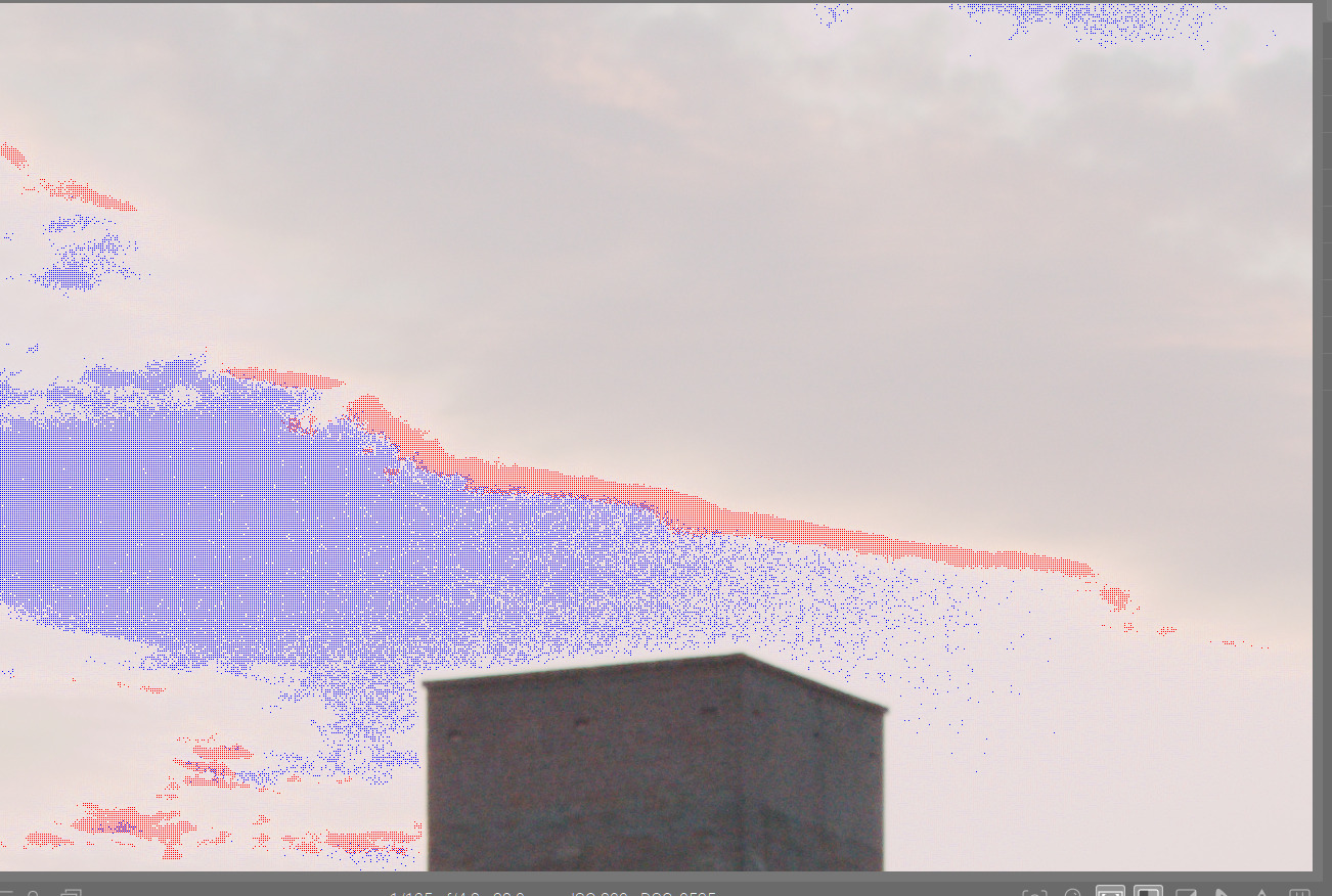
2. You will immediately see the “irregular” pattern. We see that regularly when the given whitepoint (dt gets that from exif data) is not perfect.
3. In some cases (some sonys for example are notorious for that) the exif data seem to be wrong. Also with 10bit sensors this can be seen more often.
4. When you have problems with highlights reconstruction and a) see such patterns or clearly have a magenta cast but the indicator does not show clipping you should immedately decrease the threshold value.
5. A correct threshold value will make the highlights reconstruction stepping in presenting better data to the demosaicer.
6. After selecting a proper threshold you might opt for “segmentation” and modify the candidating. If there are large areas with sensor data blown out like here, segmentation is almost always the best algorithm as it does not only correct for local data but checks for valid colors at the borders of the segments. Remember - a) if the threshold is bad the segmentation analysis will be less stable b) there is no OpenCL code for segmentation so there is a performance penalty.
7. About the demosaicers. If you have such “patterns”, the demosaicers can handle this not equally well. You can find other examples in snow fields for example. Again it’s about local non-linear data. VNG4 handles those cases better than RCD, so if you chose a dual demosaicing mode, in such flat areas we chose VNG over RCD by mixing.
8. Just a reminder, the highlights module provides a raster mask presenting the blown-out parts. I very hard cases you can use it to desaturate for example.
I hope this information helps a bit if you have problems with highlights
BTW - this is a very nice “highlights” example i have now included in my samples collection.
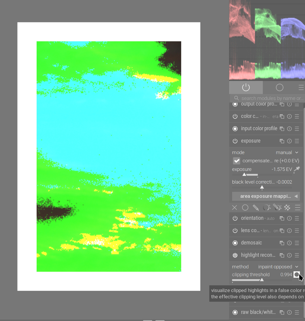
Following Hanno’s guidance (for demonstration, this is without any tone mapper, dropping exposure until highlights become clearly visible, unclipped), this is what reducing the clipping threshold in highlight reconstruction achieves (left: original threshold):
Another attempt using segmentation in highlight reconstruction after reading @hannoschwalm informative post. I feel the sky is smoother than what LR achieved and my previous DT edit. DSC_0535.NEF.xmp (22.5 KB)
I’m not convinced by any of this edits, including my own. All in all I would still think the highlight handling of LR is at least in this case a bit better.
What exactly is the irregular pattern? Could you explain what the colors mean? Black obviously signifies no clipping. Sorry, if this is obvious, but I could not find any hint in the manual.
It’s a false color representation. So green means, the green channel is above threshold. Red means, the red channel is clipped … Guess what yellow means … both red and green channels are clipped
“Irregular” insofar as for close photosites of the same “color” some are clipped and some are not. Thus you see the “noisy” false color representation. Indeed, that should be in the manual.