LUT in different color space

Hi all,
This may be a generic LUT question or it may be specific to darktable lut 3d module, not sure.

I am attempting to make a creative LUT which will give consistent results when used in different colour spaces. To do this, I made adjustments in srgb and saved to a haldclut .png, then converted that to both adobe rgb and linear rec 2020 (using elle stone’s profile), saving both as separate .png. When opened in an image viewer, all three haldcluts look exactly the same, suggesting they saved correctly. Yet when used on an image in darktable, all three give different results, despite adjusting the ‘application color space’ accordingly.

srgb:

argb:

l rec 2020:

Given all three haldcluts look exactly the same I am surprised at the differences. Is it due to quirks of the ‘application color space’ in darktable lut 3d module? Have I made a mistake? Something else?

Shouldn’t the application color space be taken from the pipeline? @anon41087856

This note was in the older manual…

Note: The color space selection is effective when lut3d module is placed between input color profile and output color profile modules. Otherwise the selected color profile is ignored, and the LUT is applied on the current profile in the pipeline.

I also found this version of the note from the original blog…

Note : This works when lut3d module is placed between input color profile and output color profile . Otherwise the selected color profile is ignored, and the lut is applied on the work profile.

So I might have misinterpreted what was meant by the first note??

  1. what is the default position?
  2. would that explain the behavior the poster sees?

I’m uncertain…following that note I would think if he set his output profile to adobe and put the adobe lut after that then if should work as he would be mapped to adobe then apply the lut to that and the setting in the box would not matter but that doesn’t answer his question… Someone who knows will likely be able to clarify this…

Some of the behavior the poster sees (the HALDs looking identical in an image viewer) would be explained by the image viewer using the embedded color profile (if present) to correct it back to sRGB

Which would indicate that the LUTs are not necessarily correct for this purpose, in that the OP seems to want:
pipeline colorspace → LUT → “creative look” in same colorspace

But what the LUT is actually doing is:
??? colorspace → LUT → “creative look” in the colorspace chosen at generation

The key here is - these three LUTs, if they look identical in an image viewer that is applying an ICC profile to transform the image data back to the display profile, are clearly expecting the same input colorspace even if their output colorspaces are different. Likely in the OP’s use case, the input colorspaces are NOT the same prior to the LUT in the pipeline

If one wants to change the “expected” input colorspace of the profile:
Generate an identity HALDclut
Assign an ICC profile to that image that matches your input colorspace/transform
Load that image in an ICC-aware image editor (dt or rt should both perform well here)
Copy your “look” adjustment history from an image you edited to taste to the haldclut
Save result

1 Like

So for DT he would set his input profile to say adobe RGB for and “adobe” lut creation?? What role does output profile play…should it match??

Then because I dont understand this stuff well enough, if you have a lut expecting adobe but your input matix is set for your camera and then that is transformed to the working space like rec2020 then what happens when you drop a rec709 or srgb LUT in the pipeline. Its not getting the right input right?? Or maybe its handled by color management somehow?? Is that what the color space selection in the module is taking care of??

I’m a bit rusty with dt (has been a while), but it SHOULD automatically set the input profile to match the icc profile of the input image. (I’m even rustier on how dt handles non-raw inputs).

I know with rt, if you apply an icc profile to an image, rt will linearize it and gamut map it appropriately. I used this (and may continue to use this) for video grading - export a frame as JPEG, apply icc profile that matches S-Log2/S-Gamut, edit to taste, then copy the processing history onto an identity haldclut that has been tagged with the same profile.

So basically input colorspace of your LUT is going to be whatever the ICC profile was of the HALD identity image (dt and rt should both be able to override it so you can choose it in the UI instead of tagging it with exiftool), and output colorspace will be whatever output colorspace you chose in the processing pipeline when you generated the LUT.

Thanks all for the suggestions. I’ve experimented a lot and still haven’t cracked the code, but am learning many things that don’t work.

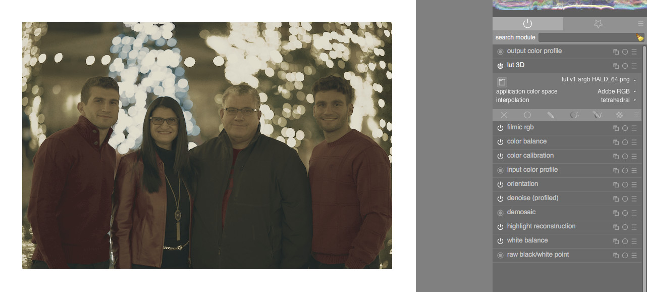
I don’t have the answer, but to guess, it is what I expect. You go from Input Profile (camera matrix) > Working Profile (user selected) > Application Color Space [when lut module is turned on] > Working Space > Output Profile (user selected). In other words, the application color space handles the transform from input > lut > output. Now it is my understanding that ‘application color space’ should match embedded profile of the LUT. png, AND/OR the assigned profile of original blank haldclut, but the below experiments don’t necessarily prove that, unless I’ve got it wrong somehow.

The image viewer is colour managed properly and is not applying any transformation back to sRGB. It displays what’s embedded. The only transformation would be to my display, which is equivalent to sRGB, but that is also true of image editors like darktable.

Experiment 1

As per original post, when ‘application color space’ is set to match embedded profile of png, and lut 3d module is placed after filmic, between input and output profile, all three look different. The one that looks most right according to expectations is the srgb lut, used with ‘application color space’ set to srgb. This is to be expected, given this lut was made from an srgb image.

Experiment 2

When ‘application color space’ is set to working profile (linear rec 2020, in this instance), and lut 3d module is placed after filmic, between input and output profile, all three look different, and wrong.

Experiment 3

Logically, this is also how I anticipate it working, but testing, when lut 3d module is moved after output profile in pipeline, the ‘application color space’ dropdown disappears. When I keep LUT the same (eg. srgb), and change output profile (eg. from srgb, to argb, to linear rec 2020), the resulting image is always the same, and wrong. When I keep output profile the same (eg. srgb) and change LUT (eg. from srgb, to argb, to linear rec 2020) the resulting image always looks different, and wrong.

However, this experiment comes with a quirk, probably a bug. If I have lut 3d placed before output color profile, application color space set to srgb, then move module after output profile, I get result X. However if I have lut 3d placed before output color profile, application space set to linear rec 2020, then move module after output profile, I get result Y. Given result X <> Y, the application space must still be taking effect despite disappearing from GUI, and I do not understand how it comes to that effect, for it does not match the results of experiment 1.

Experiment 4

I assign the blank haldclut three different spaces: srgb, argb, linear rec 2020. I apply the same preset to all three and save, with those spaces embedded. Now viewed in image viewer, each haldclut looks different.

I put lut 3d before output in darktable, open each of these three png luts with ‘application color space’ set to srgb, and they all look the same, and as expected. Hooray! But wait… this is all with ‘application color space’ set to srgb. This doesn’t seem right. Shouldn’t my srgb lut work with srgb application, argb with argb, l rec 2020 with l rec 2020, etc… ?

To test in another program, I create a synthetic gradient image and assign it three different colour spaces, then apply my luts to them. Problem is, each lut gives the same result on the same gradient, instead of different results on the same gradient, and same results on different gradient. What I mean is, the srgb lut on the srgb gradient should look the same as the argb lut on the argb gradient, and the l rec 2020 lut on the l rec 2020 gradient, etc… But that isn’t what happens.

The DT manual on ‘application color space’ doesn’t give a lot of clues. It says, “Choose the color space for which the selected 3D LUT file has been built.” But as stated, with application color space set to srgb, all of these luts now look the same despite being assigned and embedded three different profiles. So I still don’t understand.

You do realize you just contradicted yourself here by saying the image is not transformed to sRGB (or your display profile if profiled/calibrated and somehow significantly different from sRGB), and then you said it was?

Instead of screenshots of darktable, I think it would be beneficial to see the three HALDs themselves.

EDIT This one is the correct both are correct but this one but may need some update, because “work” profile may be understood as the one the user has selected as “working profile”.
Between input and output color profile, dt makes the transformation between the “working profile” and the selected one (working profile → lut profile; apply lut; lut profile → working profile).
Outside, dt just applies the LUT on the current pipeline image data, without considering any color profile.

Side note: a 3D LUT is always designed for a given color profile (or raw data) and won’t give consistent result if applied on a different one.

No, the png file profile is not considered as the lut design profile. And probably never set properly neither.

1 Like

Yup, and usually the LUT is labeled as such.

I suspect part of the problem is that the method the OP used to generate the LUT created LUTs that were effectively designed for one particular input color profile that doesn’t match the use case.

The results of the Rec2020 profile looks almost like it’s designed (probably unintentionally so) to transform some nonlinear transfer function into a linear one, and dt is assuming linear in/linear out or nonlinear in/nonlinear out. A dark image like that is a hallmark of linear data being misinterpreted as being sRGB.

We’re all just guessing until the OP provides example haldcluts. I have two guesses at the likely cause of the problem(s) (for one, if designed for different inputs they should not look exactly the same - I’m going to hold off on the other guess until I see the actual LUTs), but it will not be possible to confirm those guesses without seeing the LUT files themselves.

My point was it’s not doing anything different to darktable.

Yes, I designed this one for srgb. I was just experimenting with ways to see if it could give a consistent result in different profiles, because Luts can be time consuming to make and if I use different spaces in different programs it would be easier to convert a lut from one space to another (if possible) than to re make the lut over again.

I was also, and still am, a little confused by dt application colour space. If I want to make a lut to use accurately in dt, does that mean it must be designed specifically for one of those 4-5 application color spaces?

Got a bit on today. Will upload the luts when I can.

Note that some cLUTs are independent of device color spaces like sRGB. ICC abstract profiles for instance, are intended for application to PCS (Profile Connection Space), which is a device independent space based on CIE XYZ. This is a way of creating transforms or “looks” that can be applied to any workflow.

Yes.
We could add whatever useful color space to the list (we have put the color spaces which are commonly associated to LUTs but there is no limitation here).

If I understand properly there is still a color space (the one based on CIE XYZ) even if said “independent”.

2 Likes

Ok, I arrive with luts. The adjustments are a bit different to those above, but the methods are the same. The one that should be used as guide for ‘visually as intended’ is the the one named ‘test1…’ Along with ‘test 4’ and ‘test 5’, they were the three luts used in my initial post and ‘experiment 1’ detailed above. ‘Test 2’ and ‘Test 3’ were used in ‘experiment 4’ detailed above.

test1, input hald srgb, assigned srgb, embedded srgb

test2, input hald srgb, assigned argb, embedded argb

test3, input hald srgb, assigned l rec 2020, embedded l rec 2020

test4, input hald test1, converted argb, embedded argb

test5, input hald test1, converted l rec 2020, embedded l rec 2020

Haven’t looked at test4/test5 (need to go to work), but you were definitely not looking at test1/test2/test3 in a color managed application if they looked the same. On the forums (which I know are color managed from some previous experiments - see the panasonic V-Log thread a month or so ago), those three LUTs look different. In a non-colormanaged application (imagemagick’s display application), they look identical, which says that they had their profiles assigned after saving out image data.

It appears that what you did is assign a profile after saving them out. If you want the output colorspace to actually be what you want, you need the image to be saved out in the target colorspace. Not sure how to do that in darktable as I haven’t used it in a long time, with rawtherapee image data is automatically transformed into whatever profile you choose for output and the chosen profile is embedded.

I suspect that what you are looking for (LUTs with identical input and output colorspaces), you will need to do the following:
Generate identity hald CLUT
Assign your desired input profile to it so your editing software treats the identity LUT as being in the desired input colorspace
Do stuff (in general, it helps to edit a real image in the input colorspace to taste - in my case I’m generating LUTs to color grade Sony S-Log2/S-Gamut video so I export a framegrab with ffmpeg and assign a matching ICC profile to the exported frame.)
Apply the same processing profile operations to the colorspace-assigned HALD CLUT
Save out the result with the desired LUT output colorspace as the chosen output profile

I’ll take a look at test4/5 in more detail later, need more caffeine before I can figure out what your intent was. What I can see from quick inspection is that it looks like in addition to being Rec2020 colorspace, test5 was saved with a different transfer function too - I’m GUESSING it might be linear. For various reasons, linear in/out for a 3D LUT aren’t ideal without input/output shaper LUTs. The LUT outputting linear data explains why it’s so dark when you apply it in dt - I’m guessing dt is expecting the LUT to output something other than linear.

(Remember, the profile doesn’t just define the gamut/colorspace, but also defines the transfer function. You appear to be inconsistent about transfer function here.)

1 Like

No, it was test 1, 4 & 5 that looked the same. (Re-Edit: Yes confirm that 1,4,5 look the same both in my image viewer, firefox web browser on laptop, and colour managed editing apps. 5 looks much darker on my phone using firefox, and also in thumbnails on my desktop - so those must not be colour managed correctly)

1,2,3 were assigned profiles before being saved out. 4,5 were just test 1 saved out, Then converted to a different profile.

The only thing identical about any of these is adjustments. As above, they were either assigned or converted to one of three profiles, and saved as (embedded in output) one of three different profiles.

What I am looking for is a lut with identical adjustments that can be applied with the same visual result in a variety of colour spaces (if possible).

The steps you list to try are the steps I did, in 1,2,3.

No, the adjustments applied to each is EXACTLY the same. They all have the same tonal curve, but it is really quite a subtle one (r,g,b curves independent, so more about a colour tint than tone, although they go together). It’s a lut designed for an image that already has a tonal curve. The other adjustments I made which cause a change in brightness is that I shifted saturation and brightness together. Eg. When I desaturated a colour it got darker, and when I increased saturation it got lighter.

Sorry for hijacking. :slight_smile: Perhaps someone in this thread has answers to questions in this thread.