Yes. Second instance. First is for white balance, since I use gradient mask in second one for darkening the sky.
1 Like
Yes, but you called it color balance. Don’t you mean color calibration?
Yes. I corrected it. Sorry. 
1 Like
Yes, tone ecualizer, but with tone eq I have a problem many times:
when you select any patch in the sky all of them are in the last step of the curve.
So you cannot expand the highlights using a toot that has no control points to separate that tones.
May be it is due to the linear scence processing, but then in tone eq nodes should be not equally spaced or be shown in a logarithmic scale with morre controls in the highlights.
Your image is underexposed in general terms to not burn highlights.
And you use exposure to compensate it and the tone eq to revert it and expand lights with good result.
But that image is not backiluminated and has not so much DR than a sunset or when the subject is in the shadows.
When you have the sky overexposed (let us keep the clipping effects apart and thinkg of an image with no clipped channels).
May it be that the opposite path works?
I mean lowering exposure a bit, and using tone eq to adjust?
The use of color balance to darken the sky is providing a good improvment for the photos I have tested, thank you.
I would not like to keep talking about highlight recovery here, as it really does not too much relation with tone mapping or sigmoid vs filmic comparation.
But it @anon41087856 local contrast technics in gamma compensated work flow can produce halos, but usually in high contrast border thansitions.
Usually are selections and strong tonal changes what produces your halos.
In a sky that LR or other software recovers from one or two channels being blown you have not that problems (except if you are really mad at dramatization).
In clouds or sunsets there are no hard borders or abrupt transitions, so recovering color from neighbourhood and aplying info about luminosity from the remaining channel usually does not work bad.
In any case it works much better than having a grey patch or a magenta color where it should be a not so saturated yellow.
1 Like
If that is so like here…

…then you go to the masking tab and adjust the mask…

![]()
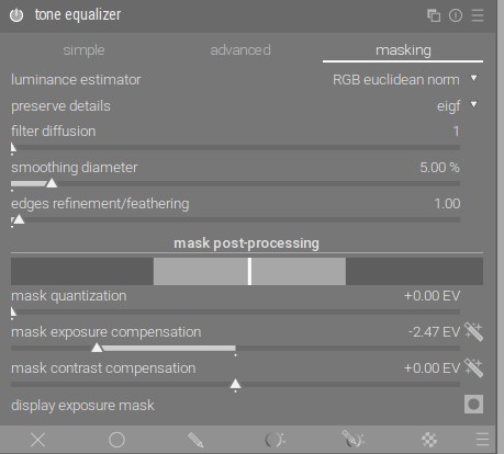
…and now you have it:

![]()
The photo is a little blurry but, before:

After:

Also done as I have described above.
5 Likes
Yes.
1 Like
Great, thank you.
Have to study it and do tries to see if I can master it.
I will put this thread in my bookmarks bag.
In my image, all samples from the sky are over the last node to the right.
But I had not used the mask postprocessing options.
One more thing to study and master, thank you.
1 Like
Again these settings and the chosen norm can impact the mask and the end result quite a bit so it is good to experient…esp is you see any halos the edge slider can be used to clean them up…
1 Like
That’s a great tutorial, Boris. I see how you used the master tab in Color Balance RGB to increase contrast, but it begs the question as to why the 4-ways isn’t used very often for that purpose?
Thanks for doing all the screenshots… I never learned so much in 5 minutes before.
4 Likes
Because the contrast you can get in the master tab by increasing the saturation is sufficient in most cases.
3 Likes
I use it in color balance rgb.
In fact that was my previous way of doing thins, playing with the silders to affect only highloghts and using a mask.
The effect is simply not enough strong to be very noticeble and counteract the inevitable strong compression of highlight in the tone mapping step made by filmic or any other curve.
1 Like
Stupid question: Is sigmoid doing anything beyond the equivalent of the “Look” tab in filmic? Is it a look tab replacement or something much more complicated? Edit: I see now, again, how intertwined the look and scene tabs are in filmic.
I have tried the method of adjusting the mask.
It works much better, you get more control over the histogramm and lets you change how that control points are distributed over the histogramm.
However I do not understand well how it works, I am doing it in a “play buttong and see what happens then” workflow xD
May be I have to read the manual in depth about tone eq to see if I get a better understanding of this.
1 Like
You likely know this…but many of the settings in RGB CB are quite conservative esp with max values…you can type in higher ones…this isn’t meant to change your workflow only to point this out on the off chance you were not aware…
This is also my preferred method, but in the end RTFM always wins. ![]()
2 Likes
Update time!
I rebased and made changes to both the color processing and the exposed options in the interface, see branch.
The following was removed:
- Pre-mapping desaturation by crosstalk. This has to be done by the user now, using f.ex. the color balance rgb module.
- Options for what to do with negative values in pixels (out of working color gamut). Default to desaturation until all values are positive or zero.
- Options for different norms in “rgb ratio”, more on that later.
I also changed the language for the color processing options to be more accurate. There are now two available options:
- per channel
- rgb ratio
These options reflect on the type of application that is used with the sigmoid curve. The per channel method has a slider for adjusting the amount of hue preservation the user wants. There are currently no options for norms in the rgb ratio method but this could be expanded later without introducing breaking changes.

The current interface for the sigmoid module.
A small showcase of the different options
First, a collection of real pictures to show what the options look like. I also include filmic rgb with “auto tuned levels” as this is what most people probably are used to. One picture per row and the columns are organized in the following order:
- Sigmoid, per channel method, with preserve hue = 100%
- Sigmoid, per channel method, with preserve hue = 0%
- Sigmoid, rgb ratio method
- Filmic rgb v5, default settings + auto tune levels


Image of a Happy Kid by @person101x


From 100% Free Raw Photos - Download Raw Files For Editing Now


Synthetic tests
Highlights


Shadows


ACES test chart
Note that the horizontal lines will desaturate nicely if the user adds just a tiny bit of desaturation before the display transfrom.


Technical description: per channel
With preserve hue = 0%
Option no for preserve color in filmic.
Apply the tone curve given by the generalized log-logistic curve on each RGB channel separately.
A nice way of showingthist is by visualizing the 2D case (bicolor?) in a scatter plot. I have rotated the plot 45 deg such that the achromatic axel (channel A = channel B) is pointing straight up. The display boundary is [0, 1] in this particular example but these bounds are of course adjustable.


The curve used here is the defaults used in the moduel [contrast = 1.6 and skew = 0.0].
Some things to note:
- All points are guaranteed to be inside the “display” gamut (actually the work profile gamut).
- Chroma and brightness are locally scaled uniformly along the achromatic axis.
- The tight clustering of points at the top is what we see as the desaturation of highlights.
With preserve hue = 100%
Hue becomes a part of the display mapping problem when we expand to three-dimensional color representation. And hue is famously twisted by the per channel method, yellow (sick, Jaundice?) faces and cyan skies are common examples. I think the severity of the twist is pretty low for a lot of images though, at least from my own observations.
One can preserve one definition of hue by maintaining the internal ratio of the RGB values. I.e. the relationship of the middle value between the min and max channels (S - scene, P - per channel mapped, Hue - hue corrected version of P )
H_{mid} = P_{min} + (S_{mid} - S_{min}) \frac{P_{max} - P_{min}}{S_{max} - S_{min}}
You have seen in my earlier posts that this produces mach bands along the primaries. Adding another constraint removes these mach bands:
H_{min} + H_{mid} + H_{max} = P_{min} + P_{mid} + P_{max} \\
H_{min} >= P_{min} \\
H_{max} <= P_{max}
Adding the constraint solves the match bands but makes some pixel outputs unreachable. There is however a nice solution, only correct for hue at the border of the working gamut and preserve both hue and the sum towards the middle. A simple blending factor can be computed using
blend = \frac{2 * S_{min}} {S_{min} + S_{mid}}
I then also added the possibility to smoothly define the amount of hue correction. I will personally probably use this for fires that are a bit too clipped and sunsets that I want to be a bit more firey. Not all the way to yellow, but a bit can have quite a nice effect. Another reason for not doing a 100% hur preservation is that adding a little bit of twist actually can compensate a bit for the Abney effect.
What could be better?
Proper decoupling of display primaries from per channel processing primaries. The module currently applies the per channel approach on the working profile primaries, typically rec2020. While rec2020 looks pretty good in most cases it would be even better to be able to select any primary for the processing and then have a robust gamut compression down to the actual output gamut. Decoupled processing and explicitly output mapping are important as the processing primaries have an effect on the final look and one might want to export to multiple targets. I have an idea for how to do this but it is also possible to non-destructively add in a later version so I’m leaving this feature out for now.
Technical description: rgb ratio
Any other option than no for preserve color in filmic
RGB ratio?
You could call this a different family of tone mappers. It only maps a grayscale version of the image using a tone curve. The color individual channels are then scaled by the same factor. The idea behind this is actually quite simple, scaling all channels with the same factor preserves the stimulus of that particular pixel. It is the same operation as when changing the exposure of the image and it works great for changing a larger region of an image as in the tone equalizer. Preserving the stimulus of a pixel means that the shape of the light spectrum is constant, but its magnitude is larger or lower.
However, preserving the stimulus of a pixel does not preserve its perceptual properties, i.e., how the pixel looks to us. The look of a pixel is dependent on both its own emitted stimulus as well as the local neighbourhood stimulus around it. So there is no guarantee of perceptual preservation when all pixels change in a different way. This is why images mapped with the rgb ratio can look desatured (white “dead” faces) even though each individual pixels stimulus has been preserved.
Visualizing the bicolor case
Given scene-referred input data (ignore the coloring for now).

A closer look at mid tones and shadows to show that the spacing is similar to the above case.

The result of rgb ratio mapping with the “norm” average results in an inverted triangle with a lot of mapped colors being out-of-display-gamut. This is what the orange coloring above also shows. Scroll up and take a look at the first figure and notice that a very small percentage of input colors actually end up mapped inside of the display-referred gamut. (The percentage of colors inside the display-gamut actually approaches zero as the scene input approaches infinity!) Note that the same will be true for all norm variants except max rgb, only the shape will be different. Euclidian will for example converge to a circle instead of a flat line. Or in other words, this is not a matter of finding the ultimate norm, it’s inherent to the method. Another important observation is that chroma and brightness are not scaled uniformly along the achromatic axis. Chroma is untouched while brightness is scaled by the tone curve.

What filmic does to deal with the out-of-display-gamut colors is to add a desaturation step after the rgb ratio mapping. Filmic drives this desaturation as a function of the norm value which means that it sometimes isn’t enough (= you get out-of-display-gamut colors) or it is sometimes too much (= bright colorful objects becomes dull but not white).
A safer could be to take the known boundary of the used norm and scale (desaturate) that down to the display-gamut boundary as seen below:

One problem with this approach is that you get discontinuous behavior for all colors of the same norm as corners of the display gamut. What I have tried to do is to re-saturate the pixels again using a hyperbolic function that defines the display boundary as infinite chroma. The effect is that the relationship of colors close to the achromatic axis is maintained at the expense of compressing the colors towards the boundary.

And finally, here is where the rgb ratio out-of-display-gamut colors end up with the per channel method:

What could be better?
I have only implemented the norm average for sigmoid so far. The other norms present in filmic rgb could also be implemented but this can be added as a later addition and would not cause any backward compatibility problems.
Next steps
- As always, try it out yourself! Easiest is to just clone my whole repository into a new folder and build from there, remember to install as a test version).
- Come back here with feedback, what do you think about how it works now. I’m especially curious about your thoughts on the preserve hue results.
- I actually feel like this is finally wrapping up to a point were I think it would make a lot of sense to merge this in some form. So I had loved to start a discussion with the darktable maintainers on what possibilities there are for that.
Cheers // Jakob
29 Likes
Thank you for the detailed write up and for persisting in this endeavour. As usual, I appreciate the pretty pictures: undergirds the explanation.
Love the work being done on this. I notice Sigmoid doesn’t set a white or black point. How does it determine where those points are?
It’s because I don’t need to define it.
The curve converges to the white and black display levels. It supports “black point = -inf Ev” and “white point = inf Ev” when talking in filmic terms. The focus is on the shape of the curve and it will reach the display levels whenever it does that. You could of course calculate a white point defined as x% away from the converge target if you need to know a white point level for applying some sort of editing.
@afre Thanks! And a good reminder, I forgot to put in credits for the pictures that aren’t mine, fixed that now!
3 Likes